
Internal combustion engine having exhaust gas bypassing control mechanism

Inactive Publication Date: 2009-04-09
KAJINO YUKIO
View PDF10 Cites 1 Cited by
  • Summary
  • Abstract
  • Description
  • Claims
  • Application Information

AI Technical Summary

Benefits of technology

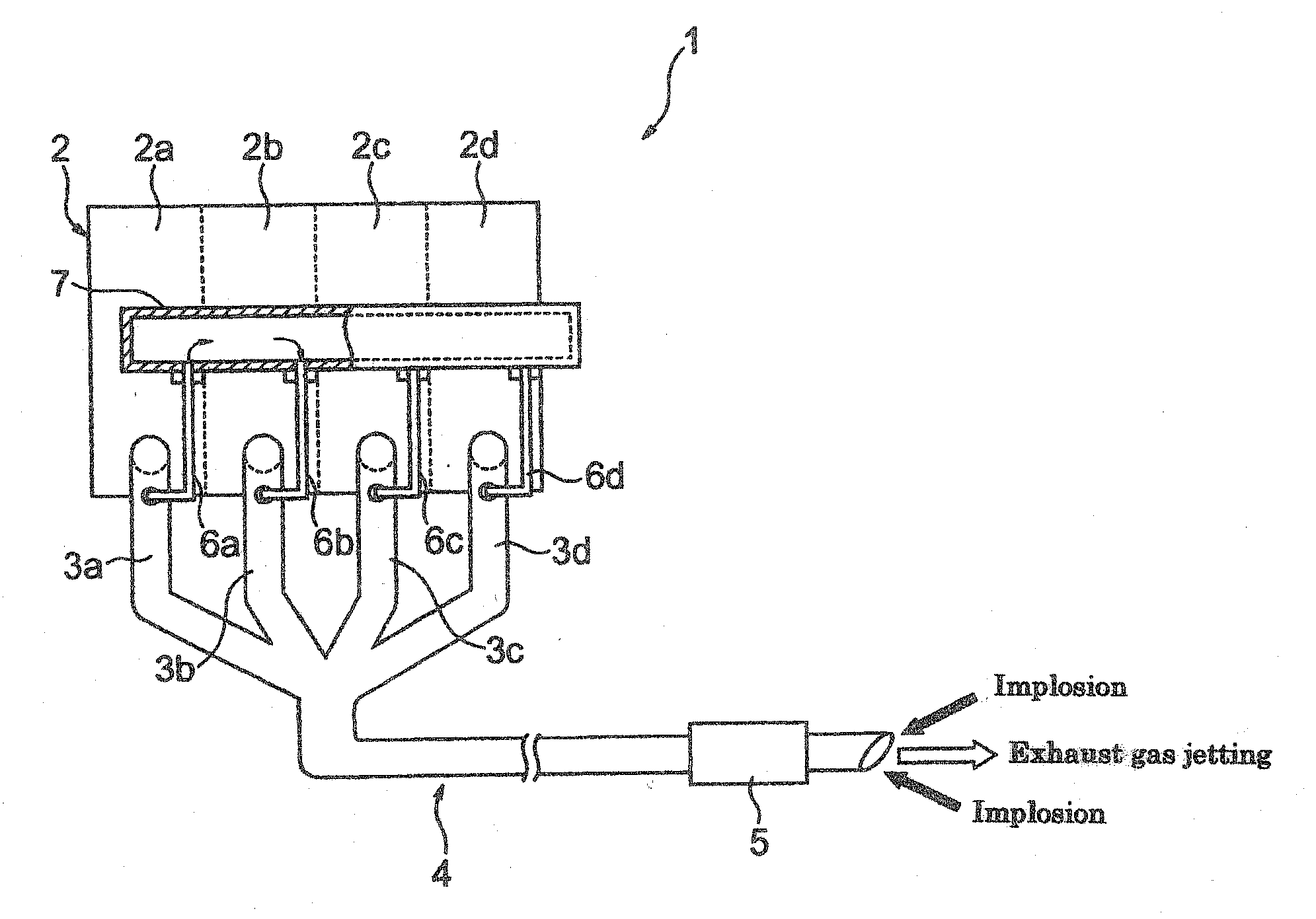
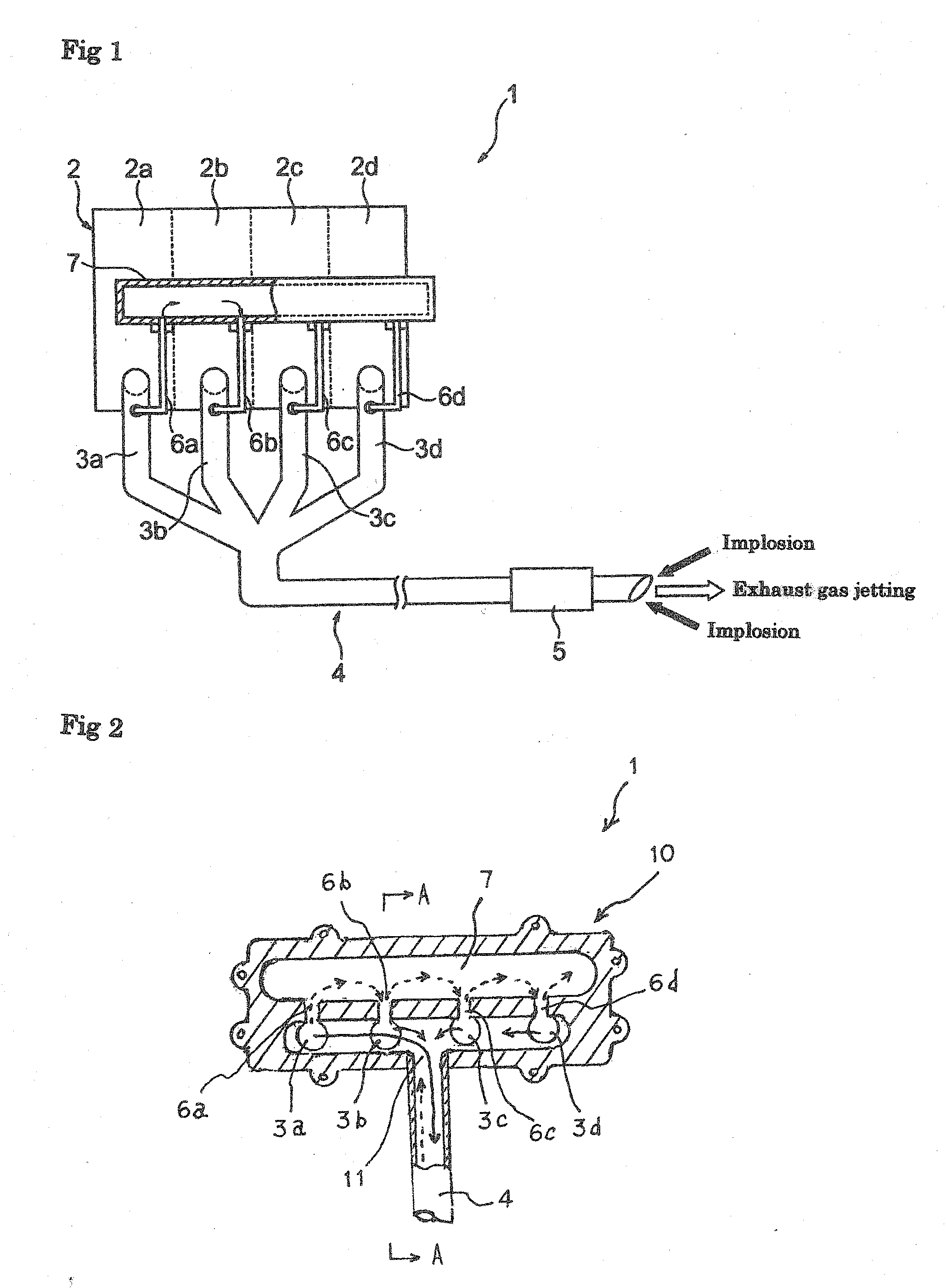
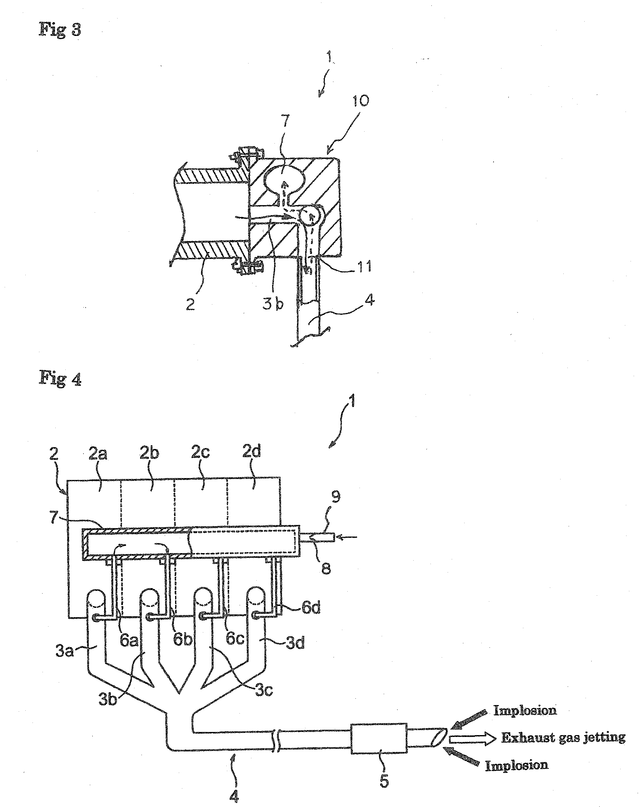
[0015]In the internal combustion engine of the invention, just after the jetting of an explosive exhaust gas, when a compressed gas caused by the implosion of a gas at the periphery of the exhaust cylinder exhaust port enters the cylinder exhaust tube during exhaustion, a portion of the exhaust gas of the cylinder exhaust tube undergoing the resistive pressure flows through the air flow passage to the common bypassing control chamber. Therefore, since the exhaust gas of the exhaust tube does not undergo the resistance of the implosion and is discharged smoothly, the engine rotation speed increases. As a result, the engine efficiency such as increase in the vehicle speed and improvement in the fuel cost is enhanced remarkably, as well as vibrations of a muffler or the exhaust tube due to jetting and implosion is suppressed.
[0016]On the other hand, a portion of the exhaust gas in the bypassing control chamber that receives a portion of the exhaust gas of the jetting cylinder exhaust tube is bypassed by the pressure increase to a low pressure cylinder exhaust tube at the instance and stays therein. In a case of incomplete combustion of the exhaust gas, when the exhaust gas at high temperature and high pressure is jetted in the next step to the cylinder exhaust tube, since the stagnating exhaust gas is burnt again and discharged by the heat of the exhaust gas at high temperature and high pressure, discharge of black smoke due to incomplete combustion is decreased.
[0017]In each of the cylinders of the engine, a fuel suction step, a compressive step, an explosion step, and an exhausting step are successively conducted instantaneously and continuously at a time interval. The black smoke is caused mainly by mixing failure of air and fuel. In the invention, since a bypassing exhaust gas circulating through the cylinder exhaust tube, the air flow passage, and the bypass control chamber flows continuously at a high speed while changing the route, air and fuel in the incomplete combustion gas are mixed uniformly in the bypassing process. Accordingly, since the factor for the incomplete combustion is removed from the exhaust gas bypassed from the bypassing control chamber to the cylinder exhaust tube and the black smoke is not generated, this provides a double effect being coupled with the suppression of the exhaust gas resistance.
[0018]Further, in a case of providing the air injection means to the bypassing control chamber, oxygen is supplied to the exhaust gas to further improve incomplete combustion.
[0019]Further, in a case of providing the alkali ingredient addition means to the bypassing control chamber, Nox in the exhaust gas is neutralized when the exhaust gas is completely burnt at a high temperature to improve the Nox content in the exhaust gas.
[0020]While the invention is applicable to any of internal combustion engines such as a diesel engine, a gasoline engine, and a gas engine, a remarkable improvement in the engine efficiency can be obtained particularly in a case when it is used for the diesel engine.

Problems solved by technology

In this case, when an explosive exhaust gas of a fuel discharged to each of cylinder exhaust tubes is jetted from an exhaust cylinder by a strong explosive pressure, surrounding atmospheric air is rapidly compressed to the center by implosion just after the explosive jetting by the reaction thereof and a pressurized gas backflows into the exhaust cylinder under the effect thereof to increase the exhaust resistance of the cylinder exhaust tube during exhaustion, which interferes smooth operation of the engine.
Therefore, this causes a problem for the engine efficiency such as undergoing restriction to the number of rotation per unit time.

Method used


Image

  • Internal combustion engine having exhaust gas bypassing control mechanism
  • Internal combustion engine having exhaust gas bypassing control mechanism
  • Internal combustion engine having exhaust gas bypassing control mechanism

Examples


experimental example 1

[0041]Car as an object of experiment: Diesel passenger car

[0042]Type of car: “Bluebird” (trade mark) manufactured by Nissan Motor Co. Ltd. in 1992

[0043]Engine mounted: 4-cycle 4-cylinder diesel engine

[0044]Total engine displacement: 1973 cc

[0045]Engine power: 4800 rpm / min, 76 Hp (in the state of new car)

[0046]Fuel cost (heavy oil): about 12 km / liter

[0047]Residual diesel black smoke concentration in exhaust gas: 55%

[0048]Vibration of exhaust cylinder: Violent vertical and lateral vibrations were observed.

[0049]An air flow passage made of stainless steel with an inner diameter of ⅓ of the inner diameter for an exhaust tube was in communication with each of the cylinder exhaust tubes of the diesel passenger car and the other end of each of the air flow passages was in communication with the tightly closed hollow bypassing control chamber disposed separately to a frame near the engine to modify into a structure of the internal combustion engine of the example shown in FIG. 1.

[0050]The r...


PUM


Abstract

[PROBLEMS] To provide an internal combustion engine enabling an increase in engine efficiency and fuel economy and a reduction in residual black smoke concentration of exhaust gas. [MEANS FOR SOLVING PROBLEMS] One end of each of air flow passages is connected to the side wall of the cylinder exhaust tube of each of cylinders, the other end of each of these air flow passages is connected to a shared bypass control chamber, and the exhaust tube of each of the cylinders is connected to each of the flow passages through the shared bypass control chamber. Thus, a part of pressurized exhaust gas in the exhaust tube of each of the cylinders brought in an exhaust step when the other cylinders are in an explosive step is discharged to the bypass control chamber through the air flow passage by the compression explosion compressive pressure of the atmosphere produced as a reaction immediately after an explosion exhaust to absorb an exhaust resistance. On the AS other hand, a part of a surplus pressure gas in the bypass control chamber is sent to the other cylinder exhaust tubes through the other air flow passages, and a fuel and an air in the exhaust gas are uniformly mixed with each other in an entire bypass step and re-burned for complete combustion.

Description

TECHNICAL FIELD[0001]The present invention concerns an improvement for an internal combustion engine such as a diesel engine, a gasoline engine, or a gas engine having a plurality of cylinders, and it particularly relates to an internal combustion engine of making discharge of a combustion exhaust gas smooth to improve the engine efficiency and drastically decreasing a residual black smoke concentration in an exhaust gas.BACKGROUND ART[0002]Internal combustion engines having a plurality of cylinders and utilizing an explosive force of a fuel in the cylinders have been generally used long since as engines for diesel cars, gasoline cars and propane cars. In the internal combustion engines of this type, independent cylinder exhaust tubes disposed to respective cylinders are in communication with a common exhaust discharge cylinder and extended backward to a vehicle and explosion exhaust gases discharged successively from each of the cylinders at a predetermined time lag are discharged ...

Claims


Application Information

Patent Timeline
IPC IPC(8): F01N7/00F01N13/10
CPCF01N13/10Y02T10/146F02B27/04Y02T10/12
Inventor KAJINO, YUKIO
Owner KAJINO YUKIO
Learn More