
Image forming method and apparatus

a technology of image forming and forming method, applied in the field of image forming method and apparatus, can solve the problems of not being able to change the height, difficult to form a three-dimensional shape with a high aspect ratio, and not being able to disclose the height direction of accurately stacking ink, etc., and achieve the effect of high aspect ratio

Inactive Publication Date: 2009-04-02
FUJIFILM CORP
View PDF3 Cites 11 Cited by
  • Summary
  • Abstract
  • Description
  • Claims
  • Application Information

AI Technical Summary

Benefits of technology

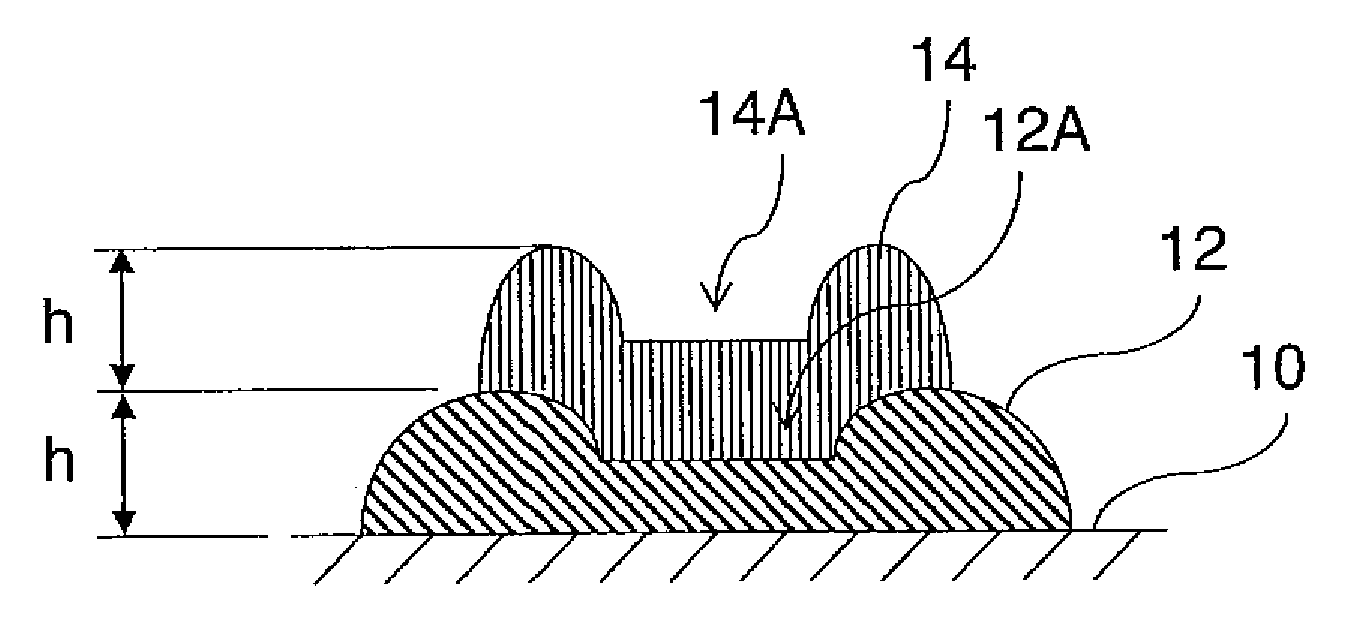
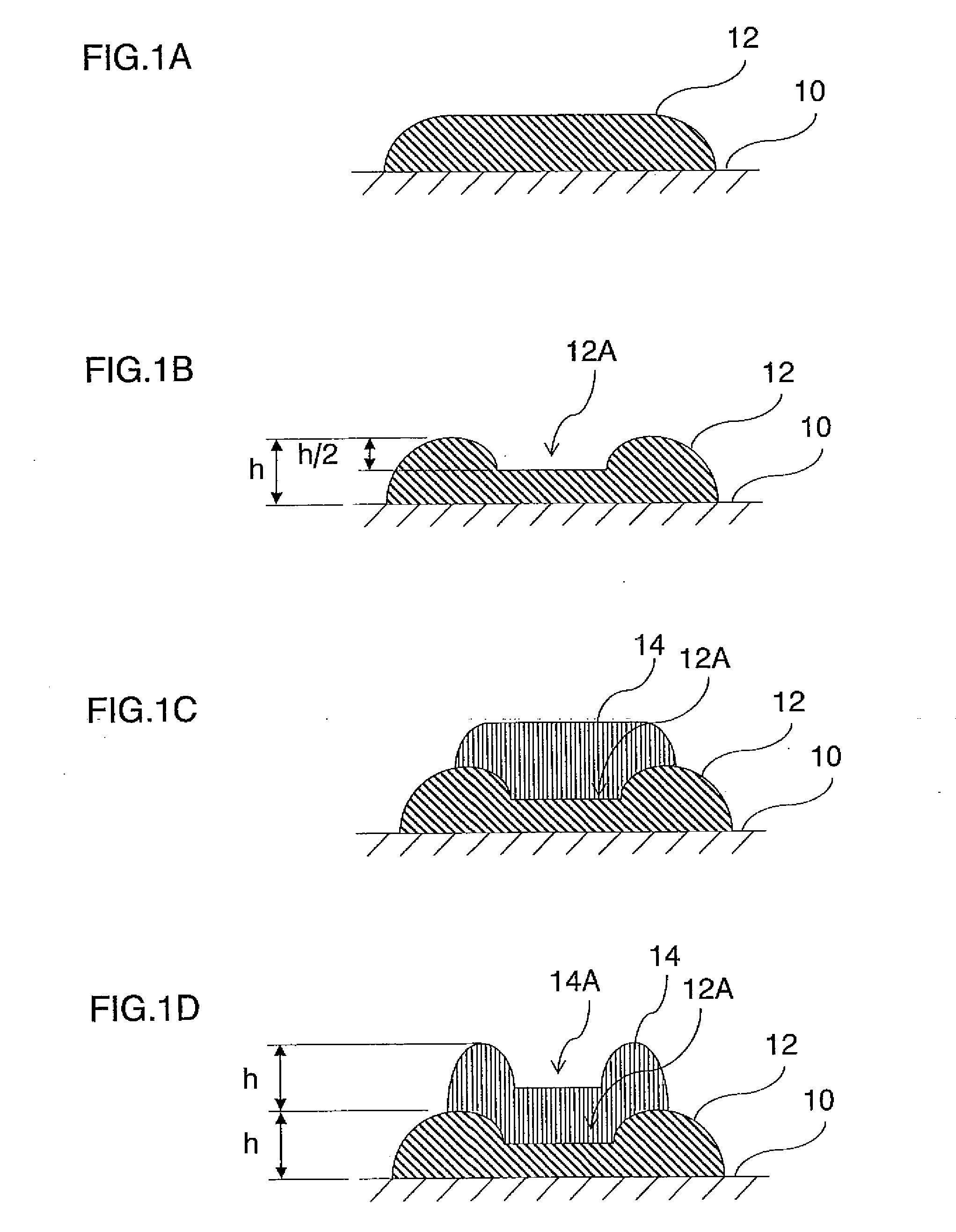
The present invention provides an image forming method and apparatus that can control the width and height of a three-dimensional shape by stacking up droplets of liquid on a medium. The invention involves depositing a first droplet of liquid onto the medium and solidifying it while maintaining an upper surface in a depressed state. This allows for independent control of the width and height of the three-dimensional shape. The invention also includes a droplet ejection control device that can control the ejection of a subsequent droplet based on the depressed shape of the previous droplet. The liquid used can be solidified by irradiating it with radiation, and the solidification can be controlled by controlling the intensity and diameter of the radiation. The invention can be used in an image forming apparatus to form three-dimensional shapes on the medium.

Problems solved by technology

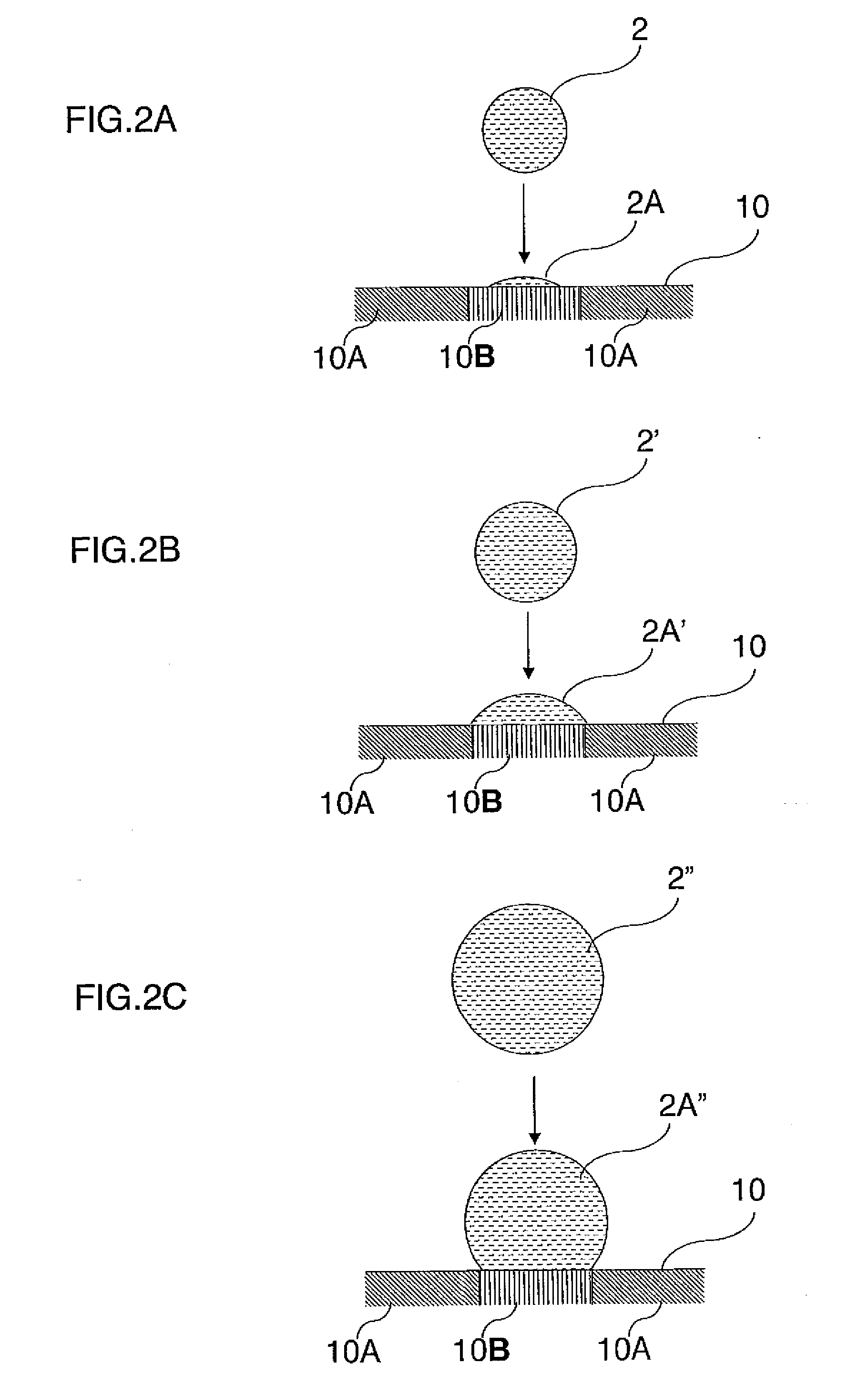
Consequently, the heights (the thicknesses) of the dots are dependent on the breadths of the dots, and it is not possible to change the heights while keeping the breadths uniform.
In other words, even if the droplets are stacked on top of each other to a great height in the height direction, the liquid spreads in the breadthways direction and therefore it is difficult to form a three-dimensional shape that has a high aspect ratio.
In Japanese Patent Application Publication No. 05-330151, although it is sought to stack ink up in the height direction by means of superimposed deposition, there is no disclosure how to accurately stack the ink in the height direction.

Method used


Image

  • Image forming method and apparatus
  • Image forming method and apparatus
  • Image forming method and apparatus

Examples


specific embodiment 1

[0055]FIG. 3A shows a state where a beam of ultraviolet (UV) light 18 is irradiated by a light source 16 from directly above (the upper side) of the droplet 12, and FIG. 13B shows the droplet 12 that has solidified in a state where the recess portion 12A is formed on the upper surface of the droplet 12.

[0056]The ultraviolet light 18 shown in FIG. 3A has sufficient strength to cause the liquid forming the droplet 12 to evaporate, and the ultraviolet light 18 is irradiated onto a prescribed region centered on the central portion of the droplet 12. Since the intensity of the light beam generally has a Gaussian distribution, then due to the irradiation of the ultraviolet light onto the droplet 12 in this way, in the central portion of the droplet 12 (the region where the ultraviolet light 18 is irradiated strongly), the solvent component on the surface evaporates off (represented with the arrowed lines in the drawing). On the other hand, in the peripheral region 12B of the droplet 12, t...

specific embodiment 2

[0058]FIGS. 4A and 4B show a further mode of the solidification process illustrated in FIGS. 3A and 3B. FIG. 4A shows a schematic drawing of a state where a needle 20 (for example, a syringe needle) having a hollow cylindrical shape is inserted into the central portion of the droplet 12 and the ultraviolet light 18 is irradiated to the side faces of the liquid droplet 12. In the state shown in FIG. 4A, the droplet 12 becomes solidified from the periphery and the ultraviolet light does not strike the portion where the needle 20 is inserted (the inner portion of the needle 20) and hence this portion of the liquid does not solidify. Subsequently, the residual liquid component in the portion where the needle 20 is inserted and the droplet has not solidified is removed, and as shown in FIG. 4B, the droplet 12 solidifies with a shape having the recess portion 12A.

[0059]The outer diameter of the needle 20 is subjected to the same conditions as those of the diameter of the light beam descri...


PUM

PropertyMeasurementUnit
temperatureaaaaaaaaaa
massaaaaaaaaaa
massaaaaaaaaaa

Abstract

The image forming method forms a three-dimensional shape on a medium by stacking up a plurality of droplets of liquid on a same droplet deposition point on the medium. The method includes the steps of: depositing a first droplet of the liquid onto the medium; then solidifying the first droplet while carrying out a process whereby an upper surface of the first droplet assumes a depressed shape; and then depositing a second droplet of the liquid onto the first droplet.

Description

BACKGROUND OF THE INVENTION[0001]1. Field of the Invention[0002]The present invention relates to an image forming method and apparatus, and more particularly, to image forming technology for forming a three-dimensional shape by stacking together layers of deposited of liquid onto a medium having non-permeable properties.[0003]2. Description of the Related Art[0004]An inkjet recording apparatus which forms a high-definition image by depositing minute droplets of ink onto a recording paper is suitable for use as an apparatus for outputting images or documents. In recent years, inkjet recording apparatuses have come to be used widely as apparatuses for outputting image or three-dimensional shapes, or the like, onto various media other than paper media, as well as apparatuses for outputting images and documents onto paper media. For example, a three-dimensional pattern can be formed on a substrate by depositing a resin liquid, or the like, onto a medium (substrate) having non-permeable ...

Claims


Application Information

Patent Timeline
Patent Type & Authority Applications(United States)
IPC IPC(8): B29C35/08
CPCB41M7/0081B41M5/00
Inventor MATAKI, HIROSHI
Owner FUJIFILM CORP
Learn More