Combustion System and Process

a combustion system and combustion technology, applied in the field of combustion system and process, to achieve the effect of greatly reducing the nox byproduct of combustion

Inactive Publication Date: 2009-04-02
BABCOCK & WILCOX POWER GENERATION GRP INC
View PDF6 Cites 4 Cited by
  • Summary
  • Abstract
  • Description
  • Claims
  • Application Information

AI Technical Summary

Benefits of technology

[0013]Briefly, the present invention provides processes and equipment for fossil fuel combustion wherein the NOx byproduct of combustions is greatly reduced, potentially eliminating the need for downstream techniques such as SCR and SNCR.
[0014]In one aspect the present invention provides a method for reducing the formation of nitrogen oxides emissions from the combustion of a fossil fuel in a nitrogen laden gas. The method comprising the steps of providing a furnace wherein fossil fuel is combusted, providing multiple rows of air fired burners, providing a row of oxy-fired reburn burners downstream of the last row of the air fired burners, providing a row of over fire air ports downstream of the row of oxy-fired reburn burners, supplying the multiple rows of air fired burners with air and a fossil fuel and a stoichiometry of less than 1.0, supplying the oxy fired reburn burners with a fossil fuel and a gaseous stream comprising at least 90% oxygen in sufficient quantity to produce a reburn stoichiometry between about 0.35 and 0.65, and supplying the row of overfire air ports with sufficient air to produce a combustion stoichiometry above 1.10 downstream of the overfire air ports.

Problems solved by technology

Based on this primary purpose, the transport gas need not contain an oxidant, although air is generally used due to cost and availability.
Conventionally, this stream has been air due to cost and availability.
This third stream, generally injected through overfire air (OFA) port, has conventionally been air due to cost and availability.

Method used


Image

  • Combustion System and Process
  • Combustion System and Process
  • Combustion System and Process

Examples


Embodiment Construction

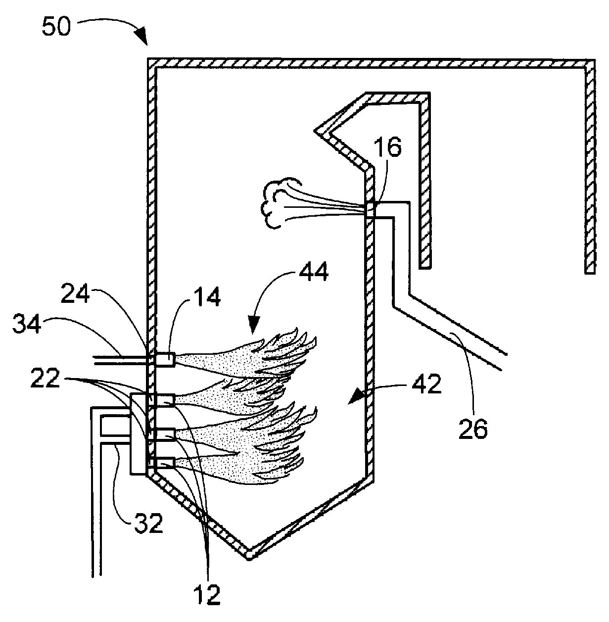
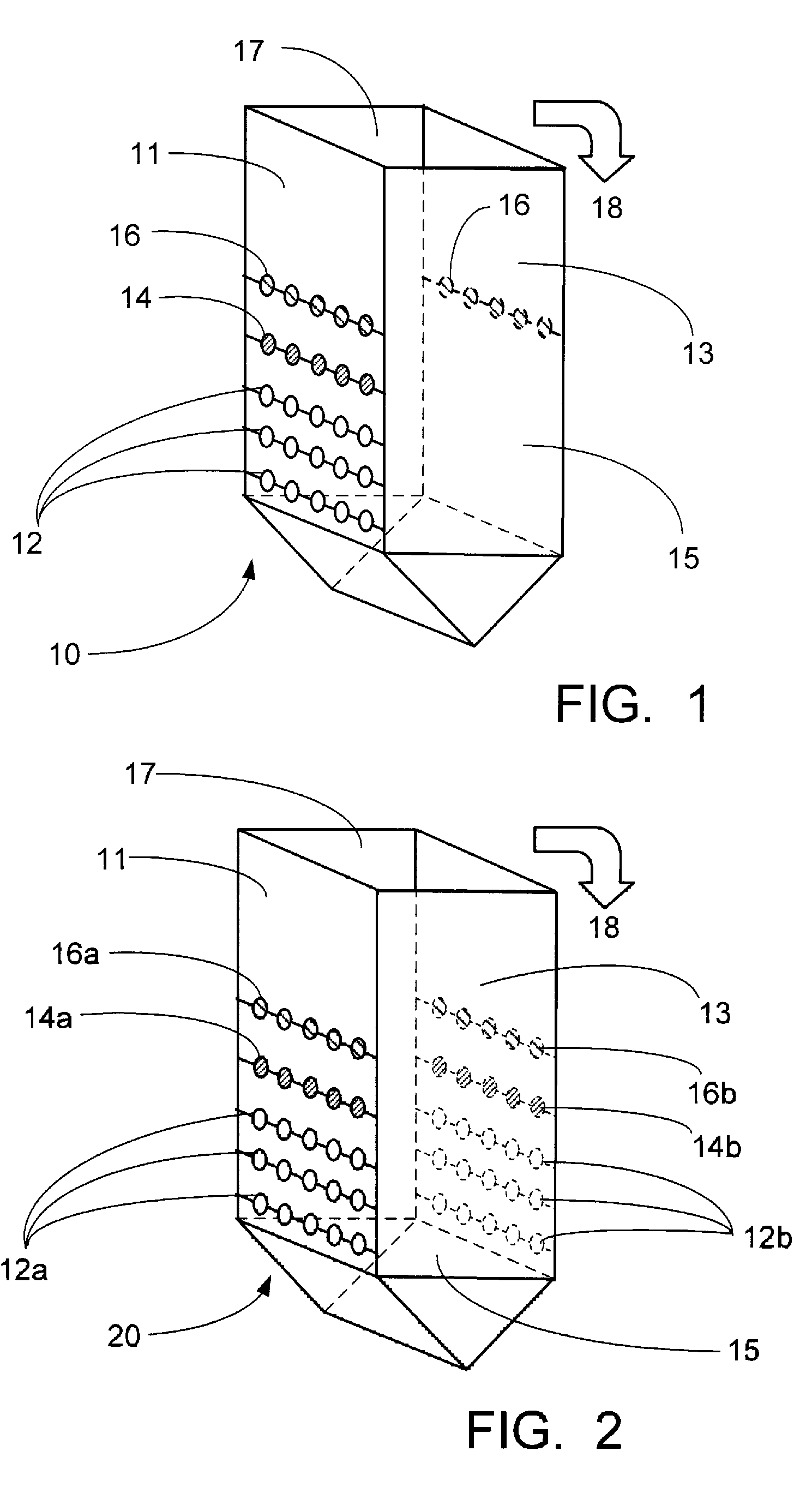
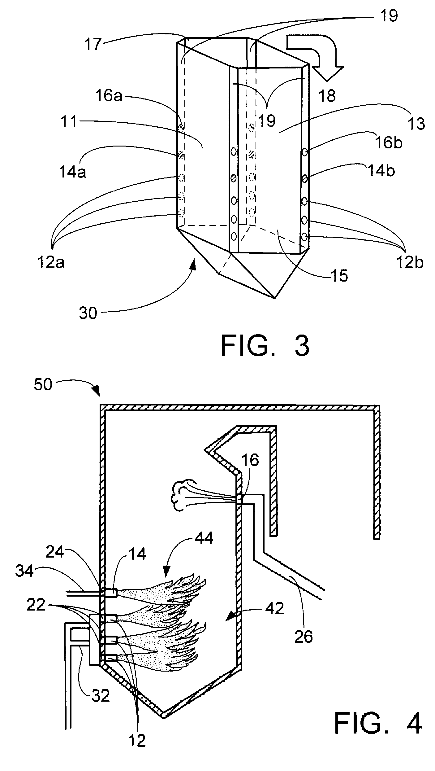
[0023]The system and process of the present invention involve air-staged furnace units capable of burning solid fuels. FIGS. 1-3 portray three relatively common solid fuel furnace configurations, each of which can be used in the present invention. Specifically, FIG. 1 is a schematic representation of a single wall-fired unit 10, FIG. 2 is a schematic representation of a opposed wall-fired unit 20, and FIG. 3 is a schematic representation of a tangential (or corner fired) unit 30. Each of these embodiments provides front wall 11, rear wall 13, and side walls 15 and 17. Tangential unit 30 also includes four corner walls 19.

[0024]Single wall-fired unit 10 incorporates primary burners 12, re-burn burners 14 and OFA ports 16 in front wall 11. Optionally, as shown in FIG. 1, additional OFA ports may be located in rear wall 13 of the single wall-fired unit. Opposed wall-fired unit 20 incorporates primary burners 12a, re-burn burners 14a and OFA ports 16a in front wall 11 and incorporates p...


PUM


Abstract

A method and apparatus for reducing NOx emissions in a coal burning furnace of a power plant without utilizing techniques downstream of the furnace, such as SCR and SNCR, is provided. In a primary combustion zone, a fuel is combusted in the presence of a first oxidant gas comprised substantially of N2, to produce a first effluent gas that include one or more NOx species. Downstream a re-burn zone is operated in a sub-stoichiometric manner, combusting a second fuel in presence of the first effluent gas and a second oxidant wherein the second oxidant gas comprises a stream of oxygen. The effluent gas from the re-burn zone is introduced to overfire airflow so as to establish a super-stoichiometric zone prior to discharged from the furnace.

Description

CROSS-REFERENCE TO RELATED APPLICATION[0001]Priority is claimed to U.S. provisional patent application No. 60 / 874,326, filed Dec. 11, 2006, the entire disclosure of which is incorporated herein by reference.FEDERALLY SPONSORED RESEARCH / DEVELOPMENT STATEMENT[0002]This invention was conceived under government contract RCD1459. The United States Government, Department of Energy, may retain certain rights to this invention.FIELD OF THE INVENTION[0003]The present invention relates in general to a method and apparatus for combusting a fossil fuel such as coal, and in particular to new and useful method and apparatus for reducing the formation of nitrogen oxides during the combustion process.BACKGROUND OF THE INVENTION[0004]The combustion of fossil fuels generates oxides of nitrogen, such as NO and NO2, cumulatively referred to as NOx. Emissions of NOx in the atmosphere are increasingly becoming a health and environmental concern. The U.S. Environmental Protection Agency (EPA) has determin...

Claims


Application Information

Patent Timeline
Patent Type & Authority Applications(United States)
IPC IPC(8): F23C5/08F23C7/00F23D23/00F23L7/00F23N3/00
CPCF23C5/08Y02E20/344F23C6/047Y02E20/34F23G7/08F23J15/02
Inventor SARV, HAMID
Owner BABCOCK & WILCOX POWER GENERATION GRP INC
Why Eureka
Try Eureka