
Injection device for the intervertebral disc

Active Publication Date: 2009-03-26
YEUNG JEFFREY E
View PDF3 Cites 14 Cited by
  • Summary
  • Abstract
  • Description
  • Claims
  • Application Information

AI Technical Summary

Benefits of technology

[0014]To repair degenerated discs, especially the problematic L4-5 and L5-S1 discs shielded between the ilia, a rigid needle punctures through the pedicle into the vertebral body. An elastically curved needle is resiliently straightened within the rigid needle. When the elastically curved needle is deployed from and supported by elements at the distal end of the rigid needle, the curved configuration resumes to puncture through the calcified endplate. A syringe filled with antacid is connected to the curved needle for injection and neutralization of the lactic acid to minimize acid irritation and pain.
[0015]In addition, the normalized pH enhances transport of sodium sulfate into the disc to promote biosynthesis of sulfated glycosaminoglycans for retaining additional water to sustain compressive loads upon the disc. As a result, excessive loading and strain on the facet joints are minimized; pain is alleviated.
[0016]A similar device can also inject polymerizing disc fillers to secure and stabilize spinal instability, minimizing strain and pain of the facet joints. After injection of the antacid or fillers, a biocompatible plug can be used to occlude the hole at the endplate, created by the elastically curved needle.REFERENCE NUMBER

Problems solved by technology

Low back pain is a leading cause of disability and lost productivity.
Currently, no intervention other than discectomy can halt the production of lactic acid.
There are multiple problems when attempting to puncture the calcified endplate as described in the prior art.
As a result, direction of puncture is likely to be deflected and endplate puncture would fail.
By increasing the sizes of the curved and rigid needles, friction between the curved and rigid needles greatly increases, making deployment and retrieval of the curved needle very difficult.
In addition, a large opening created at the endplate 105 by the large curved needle may cause Schmorl's nodes, leakage of nucleus pulpous into the vertebral body.

Method used


Image

  • Injection device for the intervertebral disc
  • Injection device for the intervertebral disc
  • Injection device for the intervertebral disc

Examples


Embodiment Construction

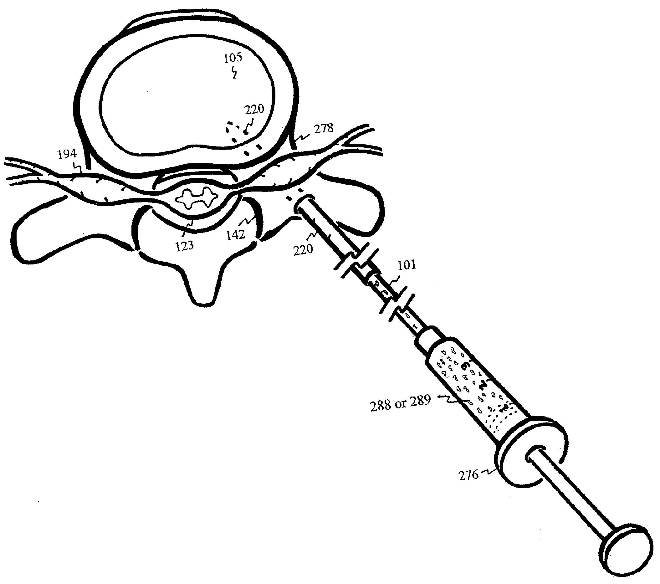
[0110]FIG. 5 shows rigid needle 220 with a syringe 276 puncturing or entering the pedicle 278 adjacent to a degenerated disc 100. Pedicle puncturing may require the guidance of fluoroscopy, ultrasound, MRI or other. In addition, trocar puncturing and / or pedicle drilling is preferred prior to rigid needle 220 puncturing. Radiopaque or echogenic coating on the rigid needle 220 and curved needle 101 enhances visual detection and ascertains device position within the vertebral body 159 during endplate 105 puncturing.

[0111]FIG. 6 shows insertion of the rigid needle 220 and elastically curved needle 101 into the pedicle 278 and partially into the vertebral body 159. The distal end of the rigid needle 220 is used to support the convex side of the deployed elastically curved needle 101 during calcified endplate 105 puncturing into the disc 100, as shown in FIG. 7. FIG. 8 shows a top view of the endplate 105 punctured by the supported elastically curved needle 101. Buffering agent 288 or fil...


PUM


Abstract

The intervertebral disc is avascular. With aging, calcified layers occlude the cartilaginous endplates, blocking the diffusion of nutrients and oxygen into the avascular disc. Under anaerobic condition, excessive production of lactic acid irritates nerves and further hinders transport of sodium sulfate essential for biosynthesis of the water retaining and load sustaining sulfated glycosaminoglycans. As the result of acid irritation and load shifting to facet joints, pain ensues. Through the pedicle, calcified endplate is punctured by a well-supported and elastically curved needle, injecting antacid to neutralize the lactic acid and enhance transport of sodium sulfate into the shielded discs between ilia. Disc filler or nutrients can also be injected through the curved needle into the degenerated disc.

Description

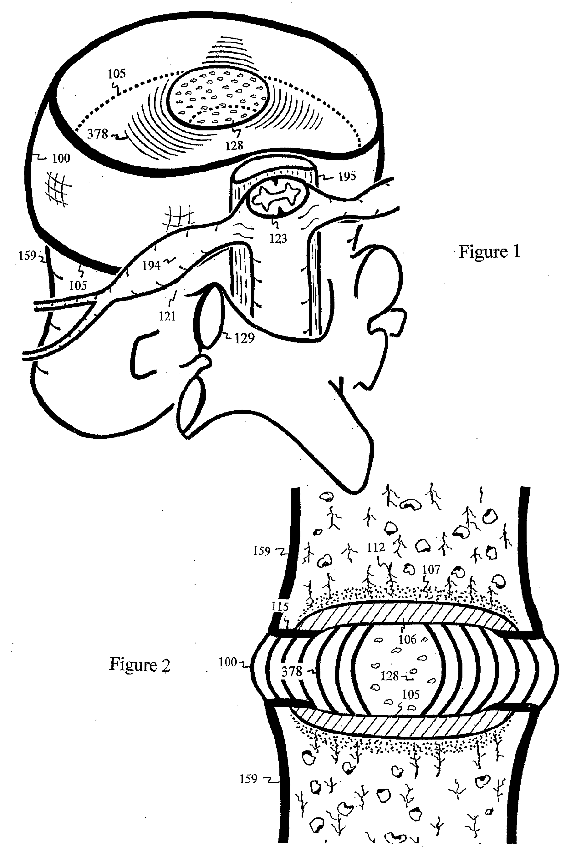
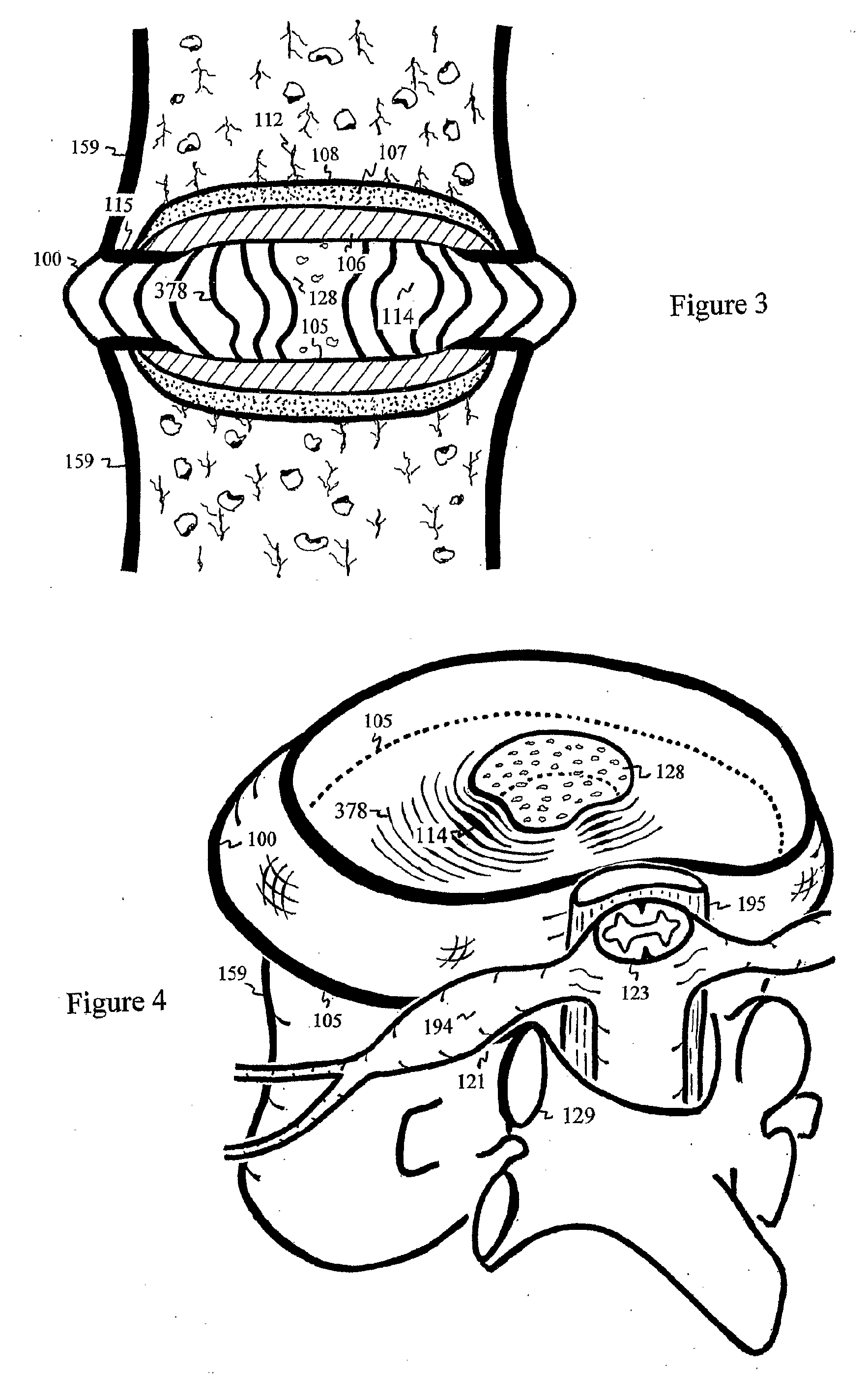
FIELD OF INVENTION[0001]This invention relates to an injection device through the pedicle into the avascular intervertebral disc to neutralize lactic acid and alleviate back pain.BACKGROUND[0002]Low back pain is a leading cause of disability and lost productivity. Up to 90% of adults experience back pain at some time during their lives. Back pain is second only to upper respiratory infections in frequency of physician visits. In the United States, the economic impact of this malady has been reported to range from $50-$100 billion each year, disabling 5.2 million people. Though the sources of low back pain are varied, the intervertebral disc is thought to play a central role in most cases. Degeneration of the disc initiates pain in other tissues by altering spinal mechanics and producing non-physiologic stress in surrounding tissues.[0003]A healthy intervertebral disc absorbs most of the compressive load of the spine. The facet joints 129 of the vertebral bodies 159 share only about ...

Claims


Application Information

Patent Timeline
IPC IPC(8): A61M1/00A61M31/00A61B17/20
CPCA61B17/3478A61B17/7061A61B2017/00867A61B2017/00575A61B2017/00654A61B2017/00261
Inventor YEUNG, JEFFREY E.
Owner YEUNG JEFFREY E
Learn More