
Phosphor-containing molded member, method of manufacturing the same, and light emitting device having the same

a technology of phosphor-containing molded parts and light-emitting devices, which is applied in the manufacture of electrode systems, electric discharge tubes/lamps, and discharge tubes luminescent screens. it can solve the problems of low-melting point glass having a poor light extraction efficiency, low-melting point glass being susceptible to heat and humidity, and epoxy resin or silicone resin tending to deteriora

Active Publication Date: 2009-03-19
NICHIA CORP
View PDF5 Cites 39 Cited by
  • Summary
  • Abstract
  • Description
  • Claims
  • Application Information

AI Technical Summary

Benefits of technology

The present invention relates to a method of manufacturing a phosphor-containing molded member with a high phosphor content using a Spark Plasma Sintering method. The method allows for a faster manufacturing process and results in a stronger and thinner molded member with high light extraction efficiency. The phosphor-containing molded member has a high phosphor concentration and is suitable for use in light emitting devices. The method also allows for the use of a glass powder in the molded member, which improves the bonding between the phosphor powder and the inorganic powder. The inorganic member can have a glass transition point of -200°C or greater, and the difference in index of refraction between the inorganic member and the phosphor is preferably 1.0 or less. The phosphor can have an average particle diameter in a range from 10 nm to -100 μm, and the method allows for uniform mixing of the phosphor and the inorganic member, resulting in a uniform emission. The invention also provides a light emitting device with the phosphor-containing molded member.

Problems solved by technology

However, deterioration in the epoxy resin or silicone resin tends to occur with higher output power of an LED chip or generated heat from an LED chip.
Moreover, the low-melting point glass has a poor light extraction efficiency.
Further, the low-melting point glass is susceptible to heat and humidity and has poor chemical stability.
Therefore, the inorganic phosphor cannot be contained at a high concentration.
Because, if the inorganic phosphor is contained at a high concentration, the emission color converting member becomes very brittle.
Fluidity of glass at a temperature lower than the softening point of the oxide glass minus 150° C. is low, so that a dense sintered compact is difficult to obtain.
At a temperature higher than the softening point thereof plus 150° C., the phosphor melts into the glass which may resulting in such as a low emission and discoloration of the glass.
In a case where the compounding ratio of the phosphor powder with respect to the oxide glass powder is high, the obtained sintered compact will be very brittle.
Thus, the emission color converting members employing phosphor powder and glass powder used in the conventional light emitting devices have problems as described above.

Method used


Image

  • Phosphor-containing molded member, method of manufacturing the same, and light emitting device having the same
  • Phosphor-containing molded member, method of manufacturing the same, and light emitting device having the same
  • Phosphor-containing molded member, method of manufacturing the same, and light emitting device having the same

Examples


examples 1 to 3

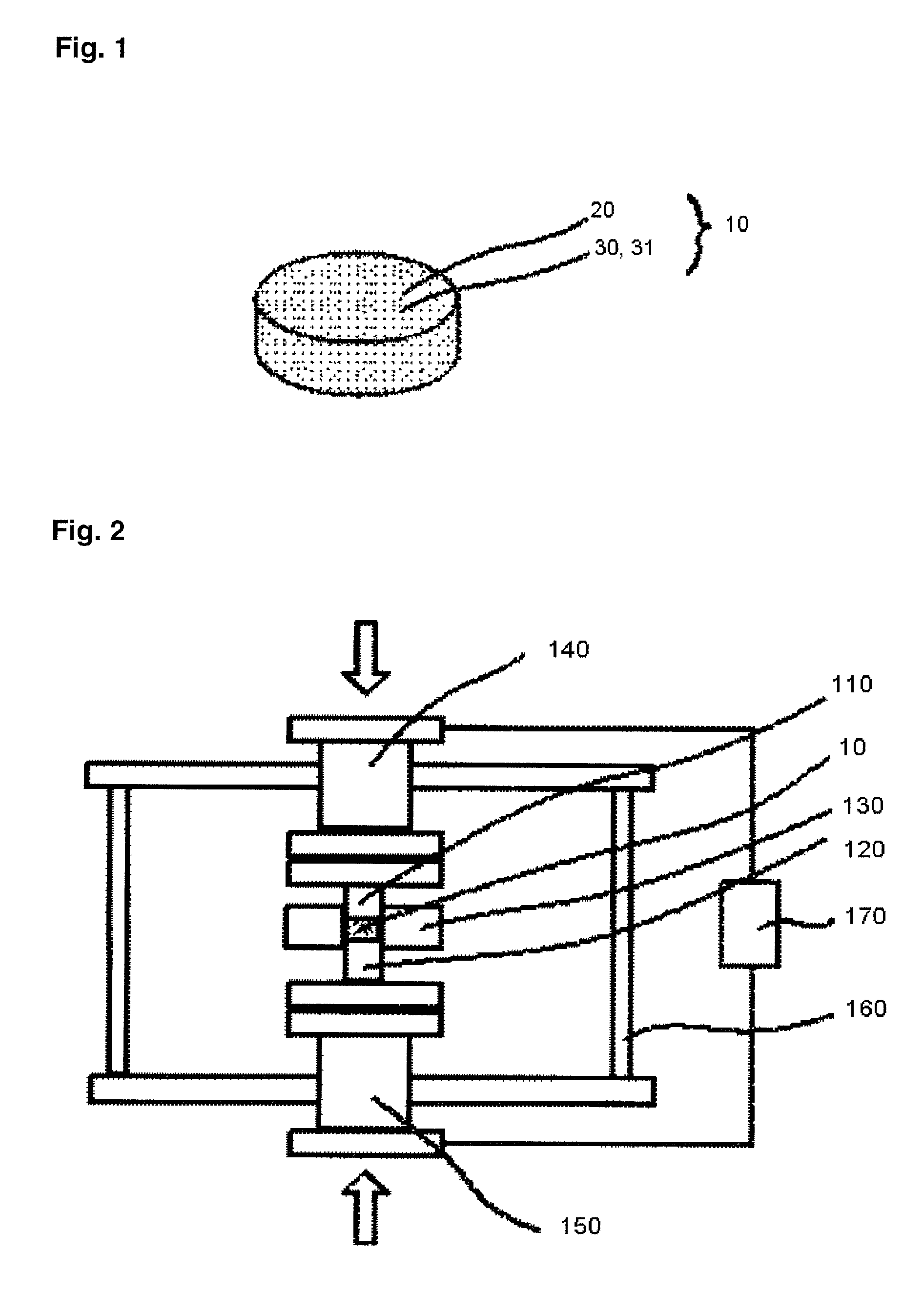
[0071]A phosphor-containing molded member according to Examples 1 to 3 will be described below. FIG. 1 is a schematic perspective view showing the phosphor-containing molded member according to the embodiment of the present invention. FIG. 3 is a schematic illustrated drawing showing a measuring method using an integrating sphere. FIG. 4 is a graph showing measurement results of luminous flux and excitation light output of a phosphor-containing molded member according to Example 2 of the present invention. FIG. 5 is a graph showing measurement results of luminous flux and excitation light output of the phosphor-containing molded member according to Example 2 of the present invention. FIG. 6 is a graph showing an emission spectrum of the phosphor-containing molded member according to Example 2 of the present invention. FIG. 7 is a graph showing an emission spectrum of the phosphor-containing molded member according to Example 2 of the present invention.

[0072]The phosphor-containing m...

example 4

[0082]Y3(Al, Ga)5O12:Ce phosphor is used for the phosphor powder 20. A phosphor-containing molded member is formed in a same manner as in Example 2, except that the raw material mixing ratio (g) of the phosphor powder 20 and the glass powder 31 using borosilicate glass is: (Y3(Al,Ga)5O12:Ce):(borosilicate glass)=15.5:84.5. Yellow emission is observed when an LED having an emission peak wavelength of 455 nm is used to irradiate the phosphor-containing molded member.

example 5

[0083]Three kinds of phosphors: Sr4Al14O25:Eu phosphor, Y3(Al,Ga)5O12:Ce phosphor, and CaSiAlN3:Eu phosphor, are used for the phosphor powder 20. A phosphor-containing molded member is formed in a same manner as in Example 2, except that the raw material mixing ratio (g) of the phosphor powder 20 using Sr4Al14O25:Eu phosphor, Y3(Al,Ga)5O12:Ce phosphor, and CaSiAlN3:Eu phosphor and the glass powder 31 using borosilicate glass is: (Sr4Al14O25:Eu):(Y3(Al,Ga)5O12:Ce):(CaSiAlN3:Eu):(borosilicate glass)=5.5:9.3:9.38:0.62:84.5. Orange emission is observed when an LED having an emission peak wavelength of 455 nm is used to irradiate the phosphor-containing molded member.


PUM

PropertyMeasurementUnit
glass transition temperatureaaaaaaaaaa
refractive indexaaaaaaaaaa
particle diameteraaaaaaaaaa

Abstract

In a method of manufacturing a phosphor-containing molded member, an inorganic powder in a mixture with a phosphor powder is melted by using Spark Plasma Sintering method, and then cooled. In a phosphor-containing molded member, a content of the phosphor therein is 5% by weight or more.

Description

BACKGROUND OF THE INVENTION[0001]1. Field of the Invention[0002]The present invention relates to a phosphor-containing molded member, a method of manufacturing the same, and a light emitting device having the phosphor-containing molded member.[0003]2. Description of the Related Art[0004]As a light emitting device using a fluorescent material or phosphor, there has been known a white light emitting device based on a combination of an LED chip emitting blue light and a YAG (yttrium aluminum oxide garnet) phosphor converting blue light to yellow light. The YAG phosphor is dispersed in an epoxy resin or silicone resin so as to be disposed around the LED chip. However, deterioration in the epoxy resin or silicone resin tends to occur with higher output power of an LED chip or generated heat from an LED chip. For this reason, there has been known a light emitting device using a glass having excellent thermal resistance and light resistance instead of epoxy resin or silicone resin, as desc...

Claims


Application Information

Patent Timeline
Patent Type & Authority Applications(United States)
IPC IPC(8): H01J1/62C09K11/80B29C35/08
CPCC03C14/004C03C2214/04H01L2924/0002C03C2214/30C04B35/44C04B2235/3224C04B2235/3225C04B2235/3229C04B2235/5436C04B2235/666C04B2235/9646C09K11/7774H01L33/501H01L33/505H01L2933/0041H01L2924/00
Inventor KAMESHIMA, MASATOSHIHOSOKAWA, SHOJITAMAKI, HIROTOICHIKAWA, MASATSUGUYAMADA, SHOICHIIWAKURA, DAISUKE
Owner NICHIA CORP
Learn More