
Buffer circuit which occupies less area in a semiconductor device

a buffer circuit and semiconductor memory technology, applied in pulse manipulation, pulse technique, instruments, etc., can solve the problems of further increasing the size of the memory chip, so as to reduce the area occupied by the buffer circuit within the semiconductor memory device, efficiently control the properties of a plurality of interface units, and reduce the effect of area

Inactive Publication Date: 2009-03-12
SK HYNIX INC
View PDF2 Cites 5 Cited by
  • Summary
  • Abstract
  • Description
  • Claims
  • Application Information

AI Technical Summary

Benefits of technology

[0031]Since the buffer circuit according to the present invention is structured such that one common bias supply unit is shared by a plurality of interface units having same property, there is an advantage in that the area occupied by the buffer within the semiconductor memory device can be reduced.
[0032]Further, the buffer circuit needs only one circuit controlling the buffer circuit, such as a reference voltage generating circuit, since the common bias supply unit is shared, making it possible to further reduce the area.
[0033]Further, since the buffer circuit is structured such that a capacitor is connected with the common bias supply unit, it is possible to protect the buffer circuit from any noise in the common bias signal using the capacitor.
[0034]Further, since the buffer circuit of the present invention is structured such that the common bias supply unit is connected with a bias control unit controlling a level of the common bias signal, it is possible to efficiently control the properties of a plurality of interface units.

Problems solved by technology

However, since the buffers are provided for each pad of the semiconductor memory device, a problem occurs in that the size of the memory chip increases due to the number of the buffers.
Additionally, a circuit (i.e., a reference voltage generating circuit) that controls the buffer is needed for each of the respective buffers, thus further increasing the size of the memory chip.

Method used


Image

  • Buffer circuit which occupies less area in a semiconductor device
  • Buffer circuit which occupies less area in a semiconductor device
  • Buffer circuit which occupies less area in a semiconductor device

Examples


Embodiment Construction

[0041]Hereinafter, preferred embodiments of the present invention will be described in detail with reference to the accompanying drawings.

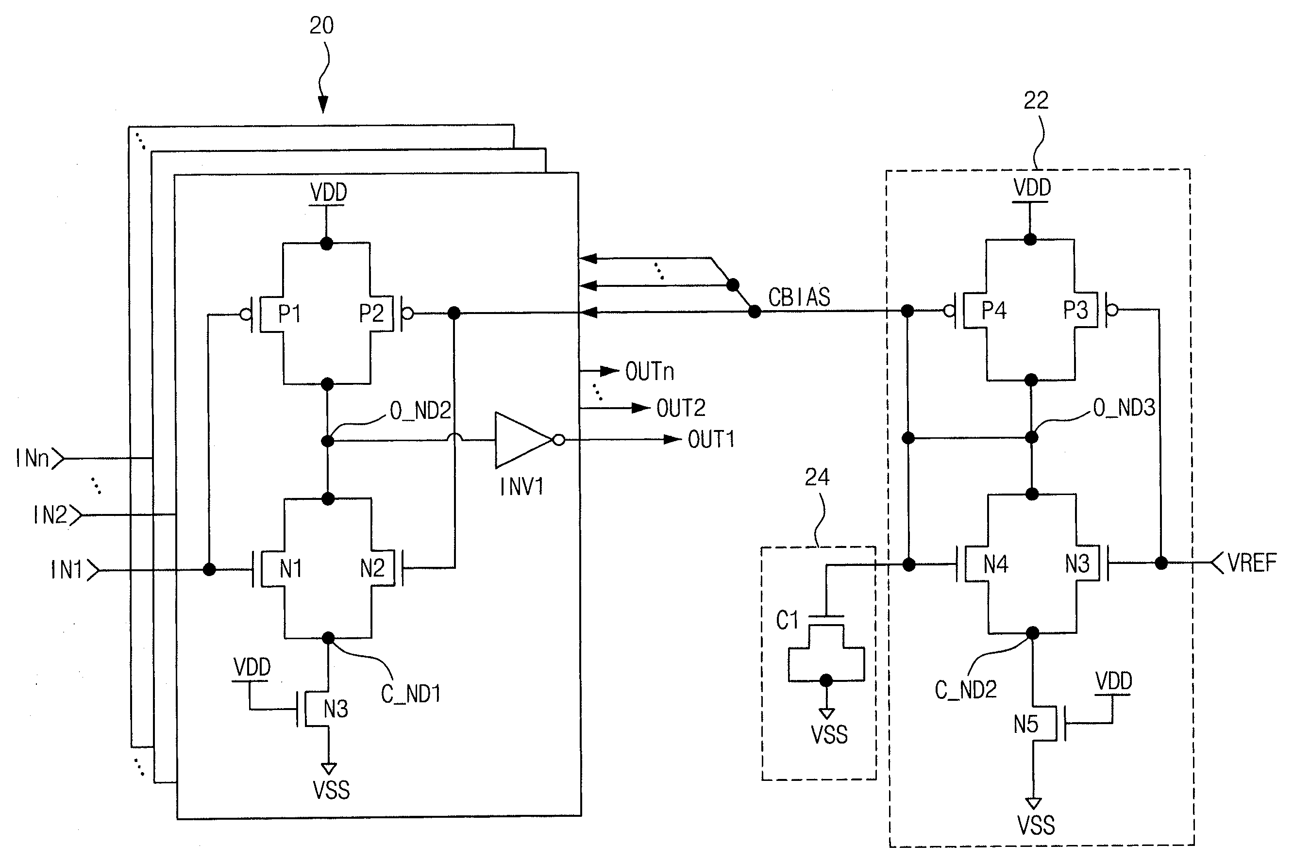
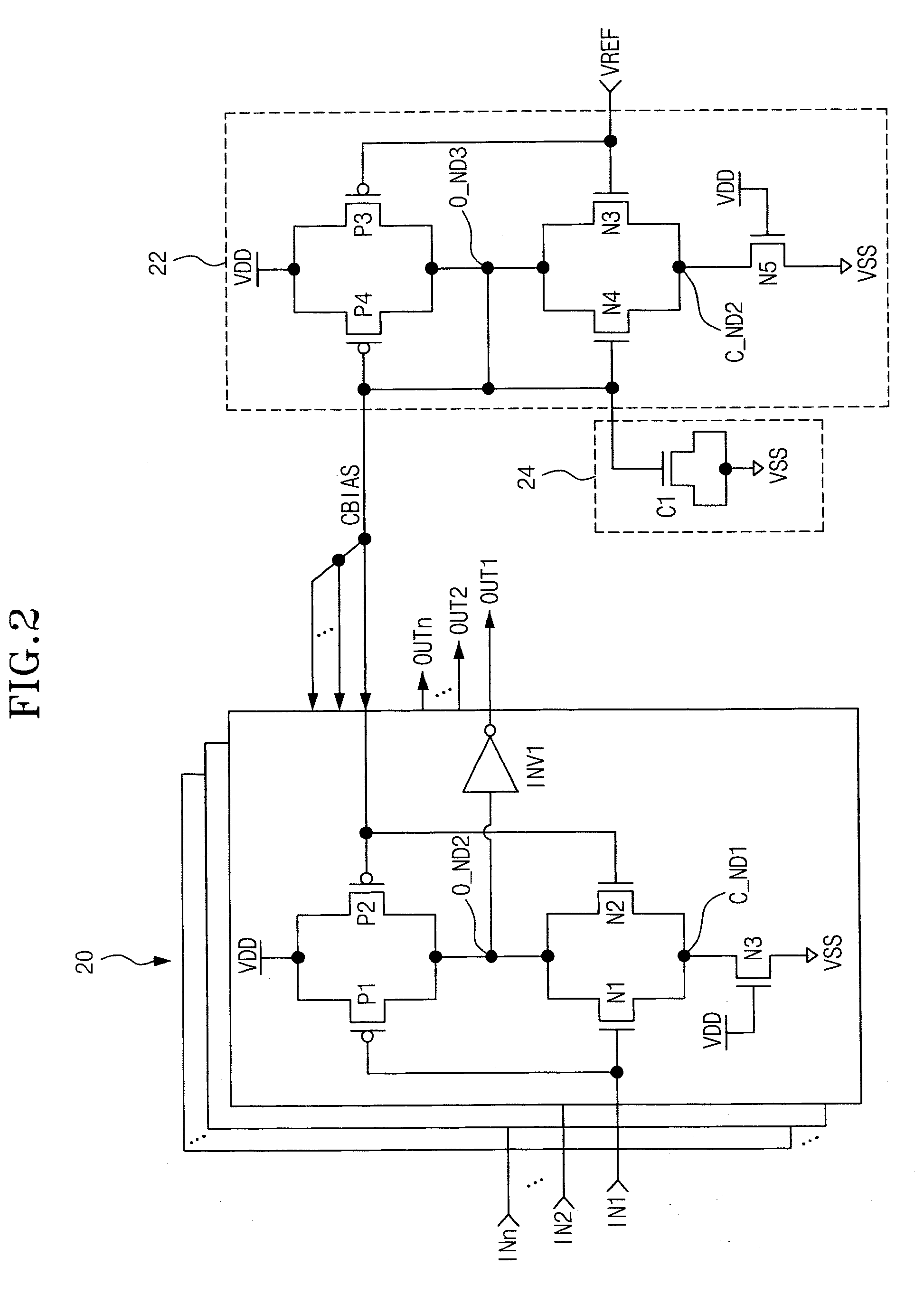
[0042]The present invention discloses a buffer circuit in which interface units outputting an output signal in response to an input signal are provided to correspond to each of the pads in a semiconductor device, and a common bias supply unit, which uses a reference signal to provides a common bias signal that controls the bias of the input signal, is shared by the interface units.

[0043]Specifically, as shown in FIG. 2, the buffer circuit of the present invention comprises a plurality of interface units 20 and a common bias supply unit 22 that is shared by the interface units 20. The common bias supply unit 22 is connected to each of interface units 20 and forms a current mirror structure with the interface unit 20.

[0044]Each interface unit 20 compares an input signal IN1˜INn input from each pad (not shown) with a common bias signal CBIAS and outp...


PUM


Abstract

The present invention relates to a buffer circuit of a semiconductor memory device, and includes a common bias supply unit and a plurality of interface units having a differential amplifying structure. Each interface unit receives an input signal and differentially amplifies the input signal and a common bias. The common bias supply unit is driven by a reference voltage to provide the common bias signal to each of the interface units. The buffer circuit makes it possible to reduce the area occupied by the buffer circuit in a semiconductor memory device.

Description

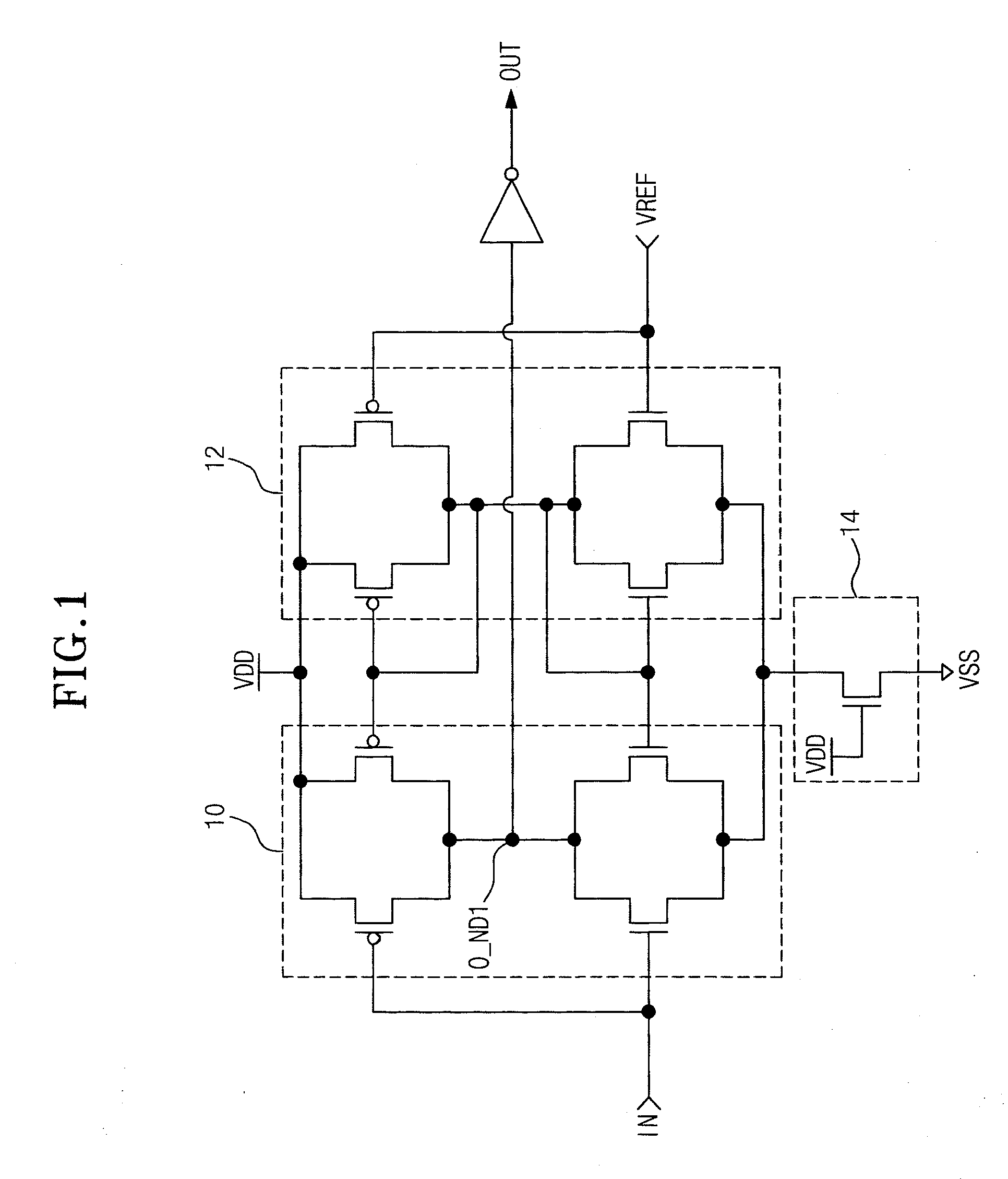
CROSS-REFERENCE TO RELATED APPLICATIONS[0001]The present application claims priority to Korean patent application number 10-2007-0091786 filed on Sep. 10, 2007, which is incorporated herein by reference in its entirety.BACKGROUND OF THE INVENTION[0002]The present invention relates to a buffer circuit, and more precisely to a buffer circuit provided in a semiconductor memory device.[0003]In general, a buffer is provided in the semiconductor memory device for the purpose of making a precise signal interface between an internal portion and an external portion of the semiconductor memory device. Further, if the semiconductor memory device interfaces the signal under conditions that are different from the conditions of the external portion, the buffer is responsible for mitigating the impacts caused by the differing conditions.[0004]FIG. 1 shows a conventional buffer that is formed with a current mirror type differential amplifying structure that compares an input signal IN to the level ...

Claims


Application Information

Patent Timeline
Patent Type & Authority Applications(United States)
IPC IPC(8): H03K3/00
CPCH03K19/018578H03K5/2481G11C7/06G11C7/10
Inventor KIM, JE YOONLEE, JONG CHERN
Owner SK HYNIX INC
Learn More