
Diagnosing malfunction of electro-optical reader

a technology of electro-optical reader and diagnostic equipment, applied in the direction of instruments, sensing record carriers, sensing by electromagnetic radiation, etc., can solve the problems of user not knowing how the system was set up or configured, data capture systems that are less than satisfactory, and many time and effort required to report problems

Inactive Publication Date: 2009-03-05
SYMBOL TECH INC
View PDF15 Cites 4 Cited by
  • Summary
  • Abstract
  • Description
  • Claims
  • Application Information

AI Technical Summary

Benefits of technology

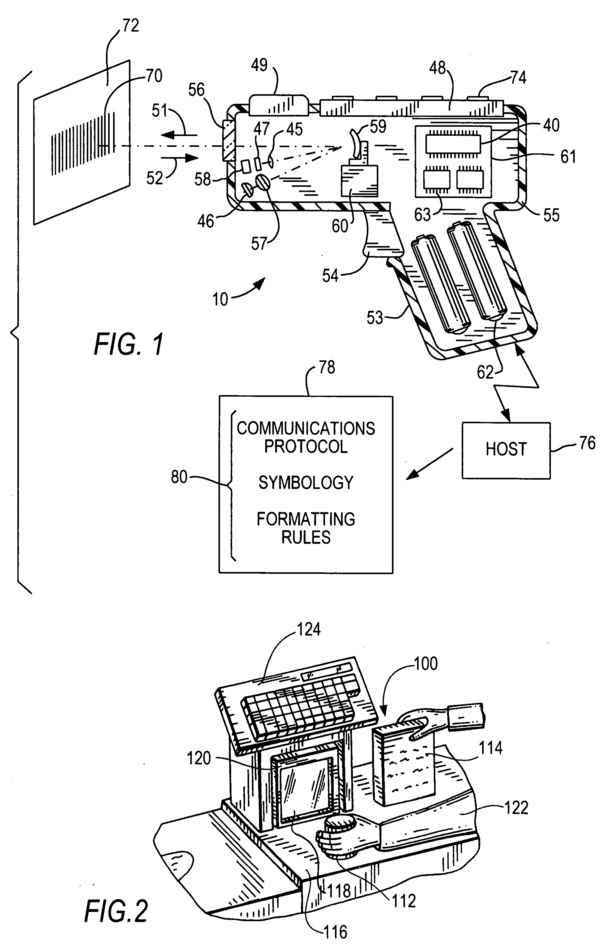
[0011]Preferably, the target is a sheet of media, and the utility datum is a bar code symbol printed on the media sheet. The media sheet may be part of an operating manual for the system, or part of an email transmission sent to the user of the system, or part of a facsimile transmission sent to the user of the system. A help desk technician may initiate the email or facsimile transmission.
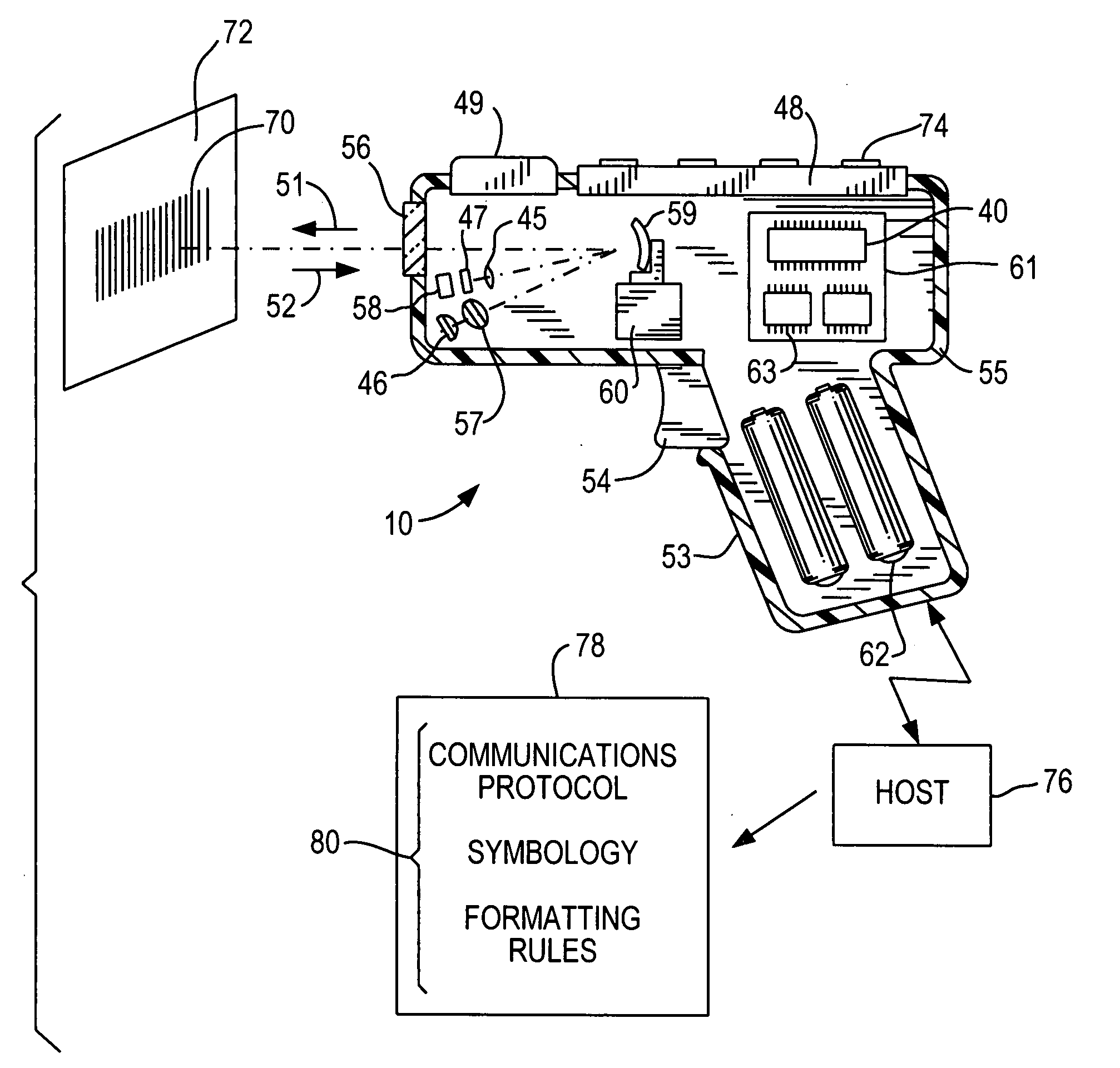
[0012]In a preferred embodiment, the controller is operative for reporting the operational settings as a text document to the host. The operational settings may include at least one of a communications protocol setting, a symbology setting, and a data formatting rule. The text document may be human- and / or machine-readable and preferably resides on the host where it can be accessed by the help desk technician for troubleshooting and diagnostic purposes.
[0013]Hence, when an operating problem arises in such systems, the system user initiates the process of reporting the malfunction to the help desk technician. It is the user, not the host, that performs the action that instructs the data capture system to output its programmed settings. The user need not, and typically does not, know how the system was set up or configured for the particular application, or what the preprogrammed settings are. It is sufficient for the technician to know that information. No special utility software needs to be loaded on the host. At most, a readily available text reader is provided on the host to read the programmed settings on the text document.

Problems solved by technology

As advantageous as such moving beam scanners and imagers are in capturing data, such data capture systems are less than satisfactory when it comes to troubleshooting and correcting malfunctions in the field.
When operating problems arise in such systems, much time and effort are required to report the problem, diagnose the problem, and service the problem.
Often, the user does not know how the system was set up or configured for the particular application, or what the preprogrammed operational settings are for normal operation.
However, this software may not be available or loaded on the host when the malfunction occurs, with the result that the malfunction remains undiagnosed and uncorrected.
This can lead to costly disruptions due to the system being out of service.

Method used


Image

  • Diagnosing malfunction of electro-optical reader
  • Diagnosing malfunction of electro-optical reader
  • Diagnosing malfunction of electro-optical reader

Examples


Embodiment Construction

[0018]Referring now to the drawings, reference numeral 10 in FIG. 1 generally identifies a portable handheld moving beam reader for electro-optically reading indica such as bar code symbols. The reader 10 is preferably implemented as a gun-shaped device, having a pistol-grip handle 53. A lightweight plastic housing 55 contains a light source 46, a detector 58, optics 57, signal processing circuitry 63, a programmed controller or microprocessor 40, and a power source or battery pack 62. An exit window 56 at a front end of the housing 55 allows an outgoing light beam 51 to exit and incoming reflected return light 52 to enter. An operator aims the reader at a bar code symbol from a position in which the reader 10 is spaced from the symbol, i.e., not touching the symbol or moving across the symbol.

[0019]The optics 57 may include a suitable lens (or multiple lens system) to focus the light beam 51 into a scanning spot at an appropriate reference plane. The light source 46, such as a semi...


PUM


Abstract

The operating parameters of data capture systems, such as electro-optical moving beam readers and imagers, are reported to a host in the event of a system malfunction by having a system operator scan a unique utility datum with the reader, or depress an actuator on the reader.

Description

BACKGROUND OF THE INVENTION[0001]Various electro-optical readers have previously been developed for reading bar code symbols appearing on a label, or on a surface of a target. The bar code symbol itself is a coded pattern of indica. Generally, the readers electro-optically transform graphic indica of the symbols into electrical signals, which are decoded into alphanumeric characters. The resulting characters describe the target and / or some characteristic of the target with which the symbol is associated. Such characters typically comprise input data to a data processing system for applications in point-of-sale processing, inventory control, article tracking and the like.[0002]Moving beam electro-optical readers have been disclosed, for example, in U.S. Pat. No. 4,251,798; No. 4,369,361; No. 4,387,297; No. 4,409,470; No. 4,760,248; and No. 4,896,026, and generally include a light source consisting of a gas laser or semiconductor laser for emitting a laser beam. The laser beam is opti...

Claims


Application Information

Patent Timeline
Patent Type & Authority Applications(United States)
IPC IPC(8): G06K7/10G06F19/00
CPCG06K7/10851
Inventor BHELLA, KENNETH S.BOOTH, EDWINAMARASEKERA, VIRAJ JEEVAN THAMEERA
Owner SYMBOL TECH INC
Learn More