
Information Recording Medium

a technology of information recording and recording medium, applied in the field of information recording medium, can solve the problems no way to know certain or easily, etc., and achieve the effect of limiting the number of reproduction times

Inactive Publication Date: 2007-09-06
PIONEER CORP
View PDF1 Cites 6 Cited by
  • Summary
  • Abstract
  • Description
  • Claims
  • Application Information

AI Technical Summary

Benefits of technology

The present invention provides an information recording medium with a substrate and a recording layer that can be limited in the number of times it can be reproduced. The recording layer can change its optical feature by being irradiated with laser light, allowing for the display or deletion of a visible display pattern that indicates the current state of the recording medium. This allows users to easily determine if the recording medium is currently in a reproducible condition or not. The information recording medium can also have a number-of-times-of-reproduction limit area in which second record information is recorded and can only be reproduced a predetermined number of times. This helps to prevent unauthorized reproduction of the recording medium. Additionally, the information recording medium can have a reproduce only area in which first record information is recorded and is not unreproducible, and a number-of-times-of-reproduction limit area in which second record information is recorded and can be unreproduced after a predetermined number of times. This allows for the reuse of the information recording medium and reduces preparation time for each recording.

Problems solved by technology

However, according to the above-mentioned hybrid type optical disc, there is still a difficulty in combination with the technology of limiting the number of times of reproduction.
Moreover, according to the optical disc on which the number of times of the information reproduction is limited, there is such a technical problem that there is no way to certainly or easily know whether the optical disc is currently in a reproducible condition or in an unreproducible condition after the reproduction is performed by a predetermined number of times.

Method used


Image

  • Information Recording Medium
  • Information Recording Medium
  • Information Recording Medium

Examples


first embodiment

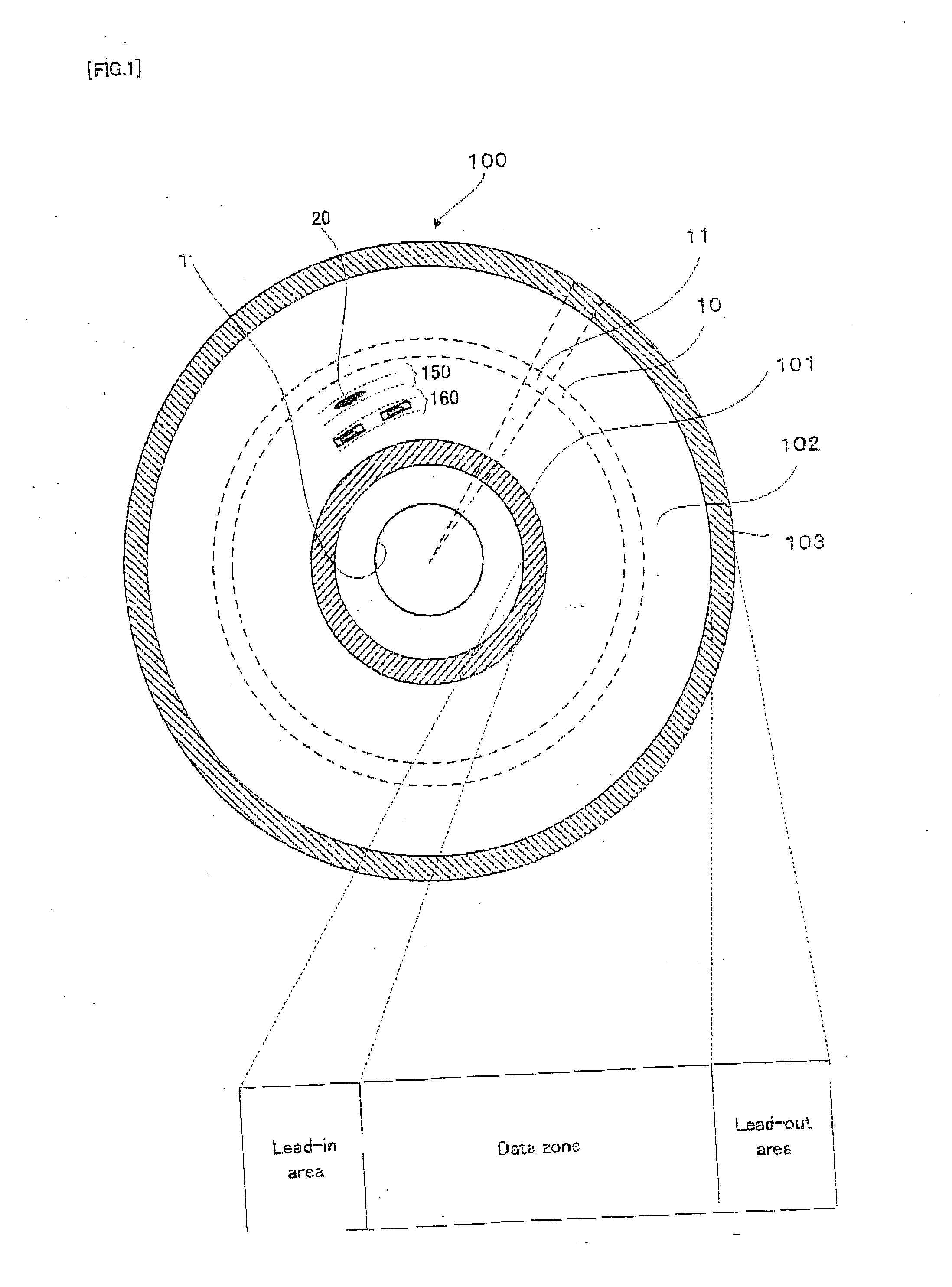
[0089] Hereinafter, the first embodiment of the information recording medium of the present invention will be explained, with reference to FIG. 1 to FIG. 7.

[0090] Firstly, the basic structure of the optical disc in the first embodiment will be explained with reference to FIG. 1. FIG. 1 is a substantial plan view showing the basic structure of the optical disc in the first embodiment of the information recording medium of the present invention, the optical disc having a plurality of recording areas, in the upper part, in association with a schematic conceptual view showing a recording area structure in the radial direction in the lower part.

[0091] As shown in FIG. 1, an optical disc 100 has a recording surface on a disc main body with a diameter of about 12 cm, as is a DVD. On the recording surface, the optical disc 100 is provided with: a center hole 1 as the center; a lead-in area 101; a data zone 102; and a lead-out area 103, from the inner to the outer circumference. In each re...

second embodiment

[0136] Next, with reference to FIG. 6 and FIG. 7 described above, as occasion demands, in addition to FIG. 8, a detailed explanation will be given for the physical structure before reproduction of the number-of-times-of-reproduction limit area and the reproduce-only area of an optical disc in a second embodiment of the present invention. FIG. 8 is a schematic structure diagram showing the cross section and the plane of the physical structure before reproduction of the number-of-times-of-reproduction limit area and the reproduce-only area (or read-only area) of the optical disc in the second embodiment of the present invention. Incidentally, the outline of a relative positional relationship or the like in the upper part and the lower part shown in FIG. 8 is the same as that in FIG. 3 and FIG. 4 or the like.

[0137] The optical disc 100 in the second embodiment of the present invention has the same basic physical features and structure as in the first embodiment, and the reflectance of...

third embodiment

[0144] Next, with reference to FIG. 6 and FIG. 7 described above, as occasion demands, in addition to FIG. 9, a detailed explanation will be given for the physical structure before reproduction of the number-of-times-of-reproduction limit area and the reproduce-only area of an optical disc in a third embodiment of the present invention. FIG. 9 is a schematic structure diagram showing the cross section and the plane of the physical structure before reproduction of the number-of-times-of-reproduction limit area and the reproduce-only area (or read-only area) of the optical disc in the third embodiment of the present invention. Incidentally, the outline of a relative positional relationship or the like in the upper part and the lower part shown in FIG. 9 is the same as that in FIG. 3 and FIG. 4 or the like.

[0145] The optical disc 100 in the third embodiment of the present invention has the same basic physical features and structure as in the first and second embodiments, and the refle...


PUM

PropertyMeasurementUnit
diameteraaaaaaaaaa
poweraaaaaaaaaa
poweraaaaaaaaaa

Abstract

An information recoding medium having a substrate (32) and a recoding layer (30) whose optical property is changed by being irradiated by a laser beam to display or erase a visible display pattern.

Description

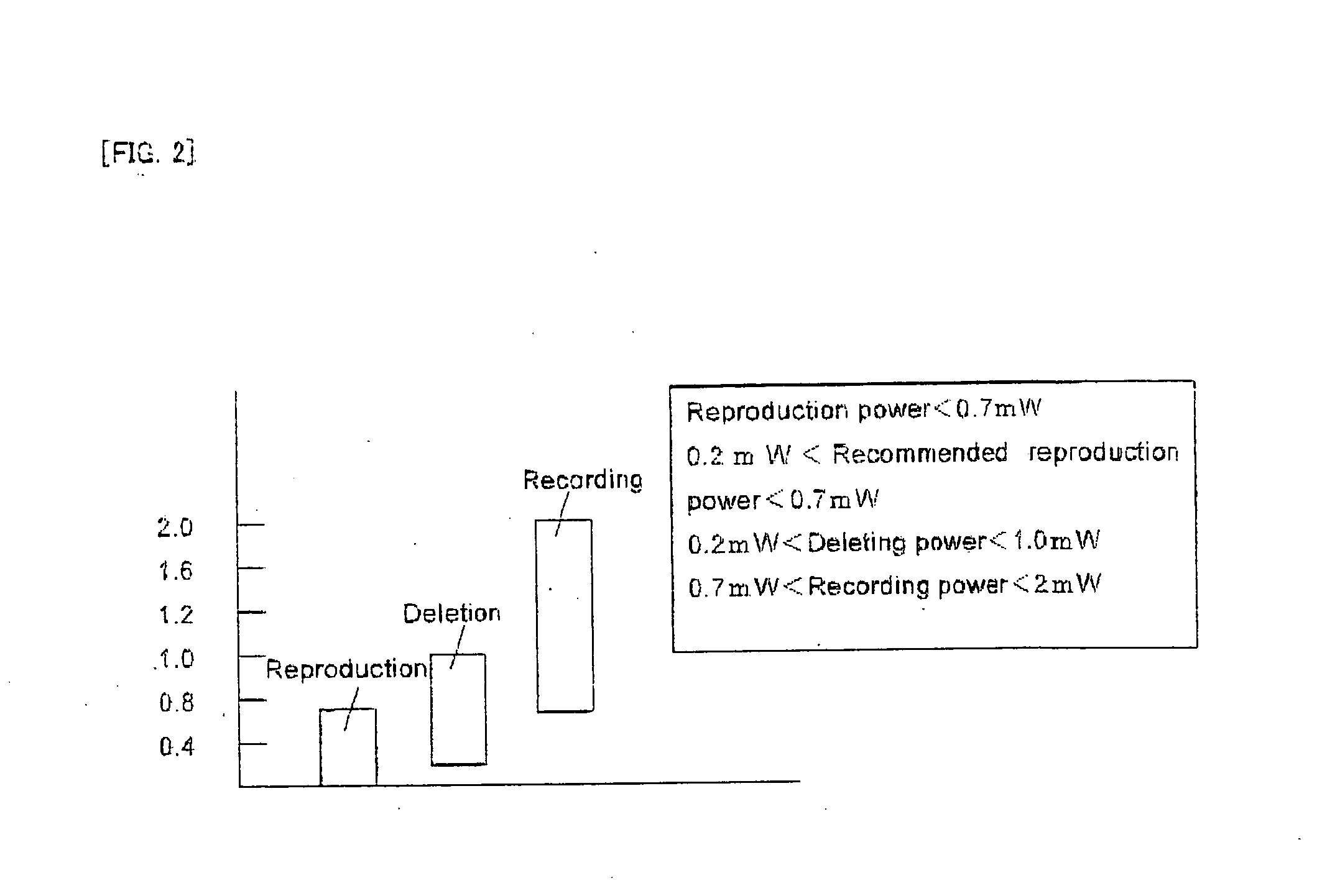
TECHNICAL FIELD [0001] The present invention relates to an information recording medium, such as an optical disc, on which recording and reproduction can be performed by irradiating it with laser light, for example. BACKGROUND ART [0002] In this type of information recording medium, in order to prevent that information is mistakenly deleted during reproduction by irradiating laser light, a range of power (i.e. energy or light intensity) of laser light in which the information can be reproduced (hereinafter referred to as a “reproduction power range” in this application, as occasion demands) is set lower than a range of laser light power in which the recorded information can be deleted (hereinafter referred to as a “deleting power range” in this application, as occasion demands). Moreover, a range of laser light power in which the information can be recorded (hereinafter referred to as a “recording power range” in this application, as occasion demands) is set higher than the deleting...

Claims


Application Information

Patent Timeline
Patent Type & Authority Applications(United States)
IPC IPC(8): G11B7/00G11B7/0045G11B7/005G11B7/0055G11B7/007G11B7/125G11B7/24G11B20/00G11B20/10
CPCG11B7/00454G11B7/00557G11B7/24094G11B20/00086G11B20/00797G11B20/00253G11B20/00586G11B20/00666G11B20/0021
Inventor KURODA, KAZUO
Owner PIONEER CORP
Learn More