Cross-flow filtration method and cross-flow filtration device

Inactive Publication Date: 2009-02-26
FUJIFILM CORP
View PDF8 Cites 5 Cited by
  • Summary
  • Abstract
  • Description
  • Claims
  • Application Information

AI Technical Summary

Benefits of technology

[0010]It is therefore an object of the invention to provide a cross-flow filtration method which is excellent in filtration accuracy and considerably improves the amount of filtration per membrane area and per unit time.
[0012]The inventor has made an intensive study to achieve the above objects and found that, by using as a membrane filter a porous alumina membrane filter made of an aluminum anodized film and having micropores whose degree of ordering, porosity and pore size standard deviation fall within predetermined ranges, the amount of filtration per membrane area and per unit time is considerably improved with higher filtration accuracy, and the invention has been completed.
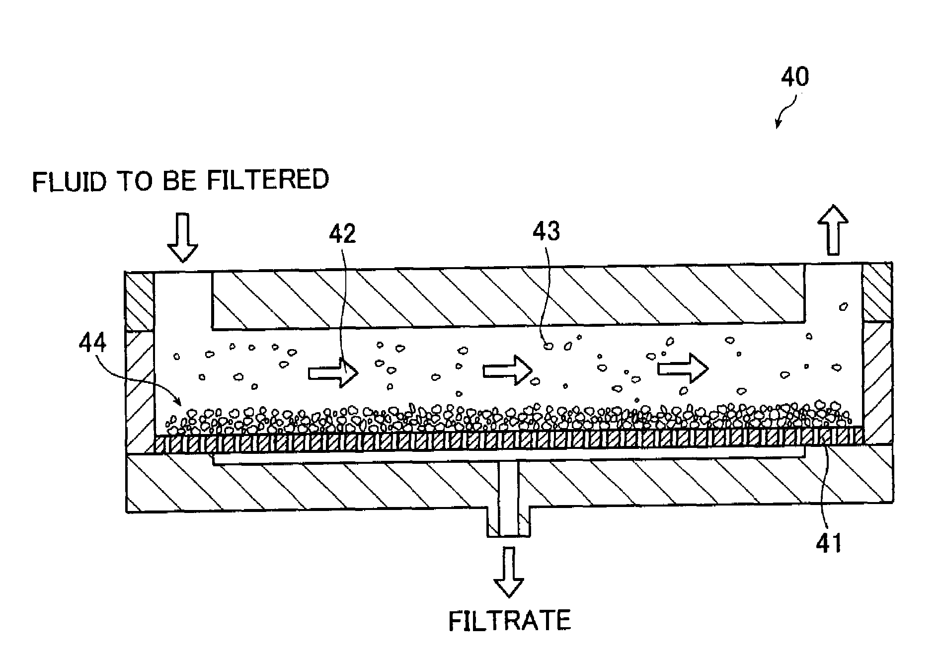
[0019]As will be described below, the cross-flow filtration method and the cross-flow filtration device that can be provided by the invention is excellent in filtration accuracy and considerably improves the amount of filtration per membrane area and per unit time.

Problems solved by technology

However, in the case of separating fine particles with a fine-structure filter, microfiltration and ultrafiltration suffered from such problems as generation of resistance in the flow of a fluid passing therethrough due to a deposit layer (cake layer) formed under the influence of concentration polarization and an increased resistance due to clogging in a membrane filter, and these problems hampered the commercialization of the filter of this type.
However, in order for the fluid to pass through the filtering medium and the cake layer to separate material suspended in the fluid, the dead-end filtration system requires a pressure overcoming the resistance of the permeating fluid caused by the cake layer.
Therefore, when applied to microfiltration or ultrafiltration, the dead-end filtration system suffered from a decreased amount of filtration (amount of permeation) per membrane area and per unit time.
However, since the membrane surface is parallel to the flow of the feed, the cross-flow filtration system is low in filtration accuracy and has difficulty in considerably improving the amount of filtration per membrane area and per unit time, and improvement methods are under study.

Method used


Image

  • Cross-flow filtration method and cross-flow filtration device
  • Cross-flow filtration method and cross-flow filtration device
  • Cross-flow filtration method and cross-flow filtration device

Examples


example 1

1. Preparation of Porous Alumina Membrane Filter

(1) Electrolytic Polishing

[0213]A high-purity aluminum substrate (Sumitomo Light Metal Industries, Ltd.; purity, 99.99 wt %; thickness, 0.4 mm) was cut to a diameter of 47 mm that allows it to be anodized, then subjected to electrolytic polishing treatment using an electrolytic polishing solution of the composition indicated below at a voltage of 25 V, a solution temperature of 65° C., and a solution flow velocity of 3.0 m / min.

[0214]A carbon electrode was used as the cathode, and a GP0110-30R unit (Takasago, Ltd.) was used as the power supply. In addition, the flow velocity of the electrolytic solution was measured using a vortex flow monitor FLM22-10PCW manufactured by As One Corporation.

Electrolytic Polishing Solution Composition:

[0215]

85 wt % Phosphoric acid (Wako Pure Chemical660 mLIndustries, Ltd.)Pure water160 mLSulfuric acid150 mLEthylene glycol 30 mL

(2) Anodizing Treatment

[0216]The sample obtained after electrolytic polishing w...

example 2

[0228]Example 1 was repeated except that an electrolytic solution of 0.50 mol / L oxalic acid was used for anodizing treatment and the voltage was 40 V, thereby obtaining a porous alumina membrane filter.

[0229]The resulting porous alumina membrane filter was subjected to shape analysis as in Example 1 and measurement of the amount of filtration per membrane area and per unit time. The results are shown in Table 2.

example 3

[0230]Example 1 was repeated except that anodizing treatment and film removal treatment were repeated three times in this order before carrying out re-anodizing treatment, thereby obtaining a porous alumina membrane filter.

[0231]The resulting porous alumina membrane filter was subjected to shape analysis as in Example 1 and measurement of the amount of filtration per membrane area and per unit time. The results are shown in Table 2.


PUM

PropertyMeasurementUnit
Fractionaaaaaaaaaa
Fractionaaaaaaaaaa
Fractionaaaaaaaaaa

Abstract

A method of cross-flow filtration using a membrane filter has a feeding a fluid to be filtered across a membrane surface of a porous alumina membrane filter serving as the membrane filter so that the fluid flows parallel to the membrane surface to separate material to be filtered with the porous alumina membrane filter. The porous alumina membrane filter is made of an aluminum anodized film and includes micropores having a degree of ordering as defined by formula (1):Degree of ordering (%)=B / A×100   (1)of at least 50%, a porosity as defined by formula (2):Porosity (%)=C / D×100   (2)of at least 40%, and a percentage of a pore size standard deviation to an average pore size of up to 10%.

Description

[0001]The entire contents of all documents cited in this specification are incorporated herein by reference.BACKGROUND OF THE INVENTION[0002]The present invention relates to a cross-flow filtration method and a cross-flow filtration device.[0003]In recent years, microfiltration and ultrafiltration technologies are increasingly applied to various fields such as protein adsorbents, water purification, air cleaning, structures for deodorization equipment, denitrification equipment and exhaust gas equipment, ozone removal, removal of various viruses, materials for clean rooms, gas separation, alkaline elution, asbestos monitoring, detection of parasites, IR spectroscopy of particles in the air, analysis of algae in a river or sea, erythrocyte deformability tests, chemotaxis and culture chambers, scanning electron microscopes, radioactive assays, exfoliative cytology and X-ray fluorescence spectrometry. In the various applications, fine-structure filters are applied to such purposes as s...

Claims


Application Information

Patent Timeline
IPC IPC(8): B01D61/14B01D39/14
CPCB01D67/0065B01D71/025B01D2315/10B01D2325/02C25D11/24C25D11/04C25D11/12C25D11/18B01D2325/021B01D2325/02833
Inventor HATANAKA, YUSUKE
Owner FUJIFILM CORP
Why Eureka
Try Eureka