
Methods of Improving thermal transfer within a hydrocarbon reformig system

a hydrocarbon fuel and thermal transfer technology, applied in the field of hydrocarbon fuel reformation, can solve the problems of only being useful in intermittent hydrogen sources, not having the ability to follow large increases in load demand, and only having the ability to meet transient load demands. the effect of improving the ability of the hydrocarbon reforming process

Inactive Publication Date: 2009-02-26
CBH2 TECH
View PDF4 Cites 6 Cited by
  • Summary
  • Abstract
  • Description
  • Claims
  • Application Information

AI Technical Summary

Benefits of technology

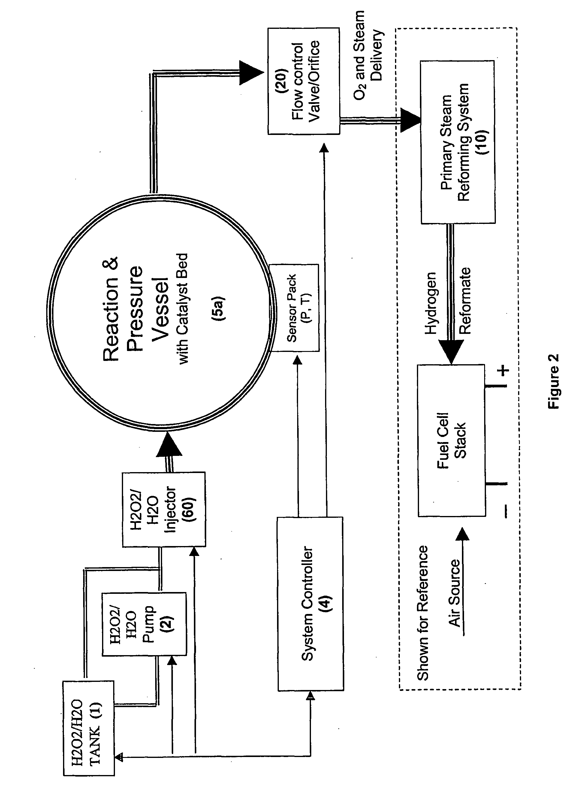
[0012]The present invention provides methods of using hydrogen peroxide to aid and improve the ability of a hydrocarbon reforming process to meet fast startup and dynamic changes in hydrogen production.

Problems solved by technology

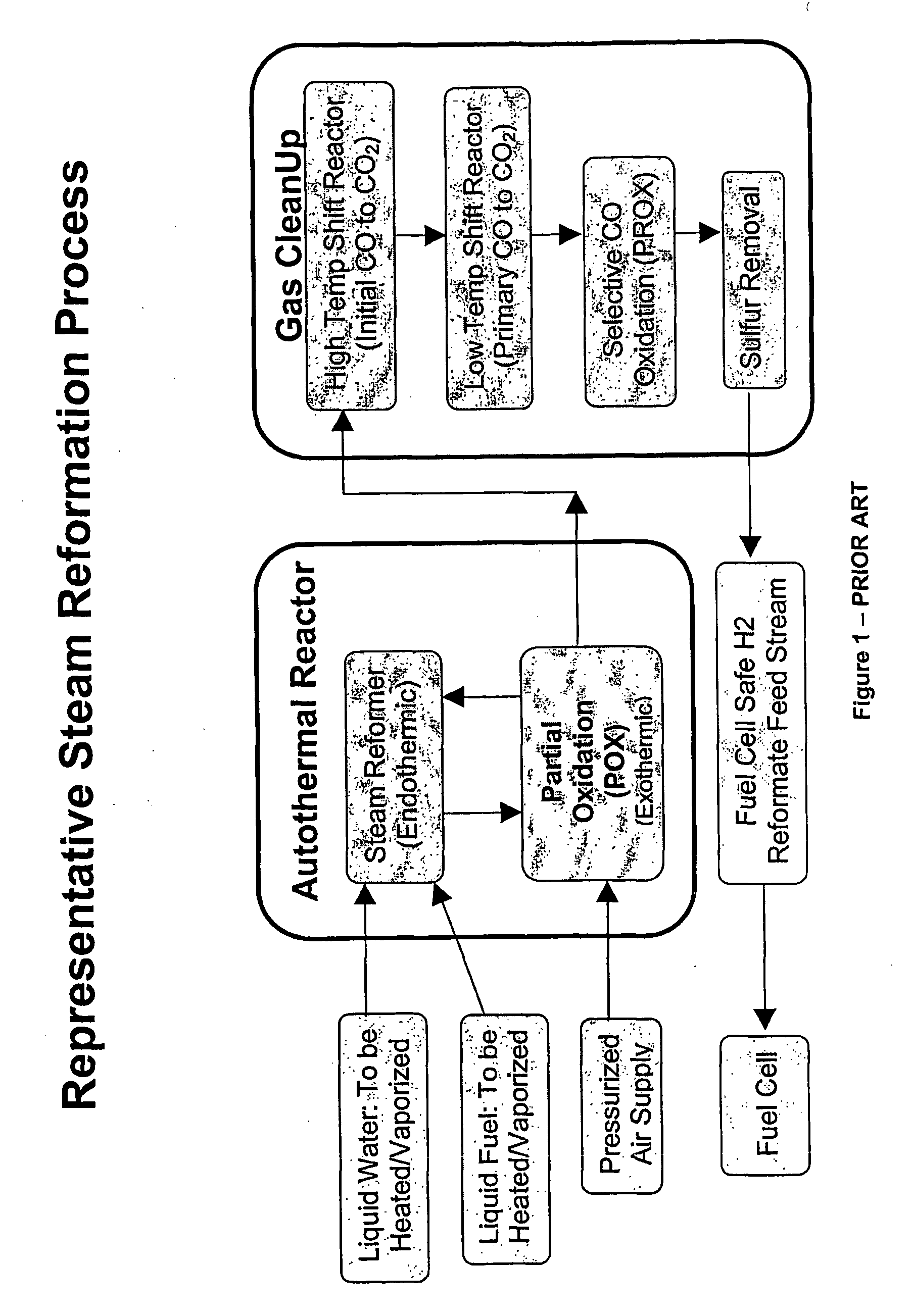
A problem with using an endothermic reforming process is that this type of system does not have the ability to follow large increases in load demand.
However, even for these applications, meeting transient load demands is still problematic due to the inherent endothermic investment that needs to be made at the very beginning of the reforming process.
While it is certainly possible to store a portion of the gaseous hydrogen feed stream in this manner, this intermittent hydrogen source is only useful in meeting dynamic load demands placed upon a Fuel Cell Power System (FCPS).
This approach does not provide any assistance in overcoming the fundamental problem of steam reforming, which is the up-front endothermic investment required to create a subsequent increase in overall hydrogen production.
Traditional as well as newer steam reforming processes also suffer in their ability to respond to rapid increases in hydrogen demand due to the significant cleanup difficulties of the reactant gases.
While this source is readily available, the component makeup of air causes significant problems in these systems.
This low oxygen ratio causes several problems including the formation of undesirable chemical compound formations.
One particularly significant problem is that steam reforming requires that the air be compressed to differing pressures depending upon the particular steam reforming process being utilized.
Small-scale gas compression, required for FCPS output, ranging from 5 kW to 500 kW is typically inefficient, resulting in large parasitic electrical loads to the FCPS.
The large presence of nitrogen in the air also increases parasitic energy losses from the compressor, because the nitrogen must be compressed as well.
The presence of nitrogen leads to other undesirable consequences in a typical steam reforming processes.
One of these undesirable consequences is the chemical formation of nitrogen-oxides (NOx), primarily NO and NO2.
The formation of these compounds in turn causes two other problems with respect to overall system efficiency.
First, NOx is a heavily regulated pollutant and must be catalytically cleaned in an elevated thermal environment.
This process further consumes hydrogen as the oxygen bonds are stripped from the NOx as it progresses to a final mixture of N2+CO2+H2O, Second, NOx formation causes the loss of available oxygen to fully oxidize carbon, which releases the sought after hydrogen.
Consequently, the steam reforming processes which use air, experience further increases in parasitic compressor losses when additional air is compressed and introduced into the overall process to compensate for the loss of oxygen due to NOx formation.
Carbon Monoxide (CO) concentrations above a few parts per million are unacceptable to the long-term reliability and durability of the PEM Membrane Electrode Assembly (MEA).
When air is used as the oxygen source, the presence of nitrogen not only creates the previously described NOx pollutants, but also further encourages the formation of CO due to the reduced availability of oxygen to fully react with the carbon.
Thus, as the bed mass increases, it will take longer to elevate the bed, or a new section of the bed, to the necessary temperature.
Until this event occurs, the product gas stream can not be supplied to a PEM fuel cell due to the contamination caused by the excessive CO levels.
This high CO gas stream must be diverted away from the fuel cell, once again inhibiting the reformer's ability to meet sudden increases in hydrogen demand as well as further deteriorating the reformer's overall conversion efficiency.
A downstream hydrogen reformate holding tank is only able to provide a limited amount of time for the primary reforming system to boil additional water.
Another considerable obstacle that must be addressed in configuring a hydrogen or reformate holding tank is that while it is possible to supplement the hydrogen source for the typical duty cycle, it becomes much more difficult to do so when non-typical duty cycles are considered.
While this is possible, the size increase adds to the cost, complexity and maintenance of the entire fuel delivery system.
Another difficulty that steam reforming faces is the limited degree of adjustability in the output rate of the hydrogen reformate.
While it may be possible to improve the reformer's turndown, there are fundamental obstacles that resist this change.
For applications requiring a fast startup and electricity delivery capability, this delay in electrical power generation is unacceptable.

Method used


Image

  • Methods of Improving thermal transfer within a hydrocarbon reformig system
  • Methods of Improving thermal transfer within a hydrocarbon reformig system
  • Methods of Improving thermal transfer within a hydrocarbon reformig system

Examples


Embodiment Construction

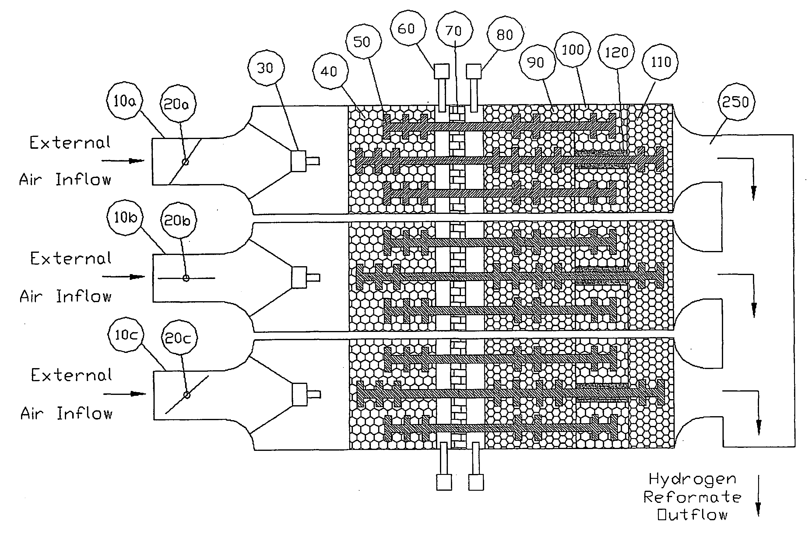
[0028]The ability of an air based reforming system to respond to any increase in hydrogen production demand is highly dependant upon that system's ability to provide appropriate thermal increases to the water feed stock, catalytic beds and other thermal masses of the containment components. The rate at which the thermal management system must respond is identical to the rate at which demand for hydrogen production changes. One system level approach to supplying more hydrogen for transient load increases, while the reformer's thermal management system struggles with maintaining the necessary process conditions, is to produce and store excess pressurized hydrogen in holding tanks.

[0029]An alternative approach to obtaining supplemental hydrogen from a holding tank would be to introduce a supplemental, exothermic oxygen source at the beginning of the primary reforming process. To be effective, the oxygen source would ideally need to be free or substantially free of contaminates such as ...


PUM

PropertyMeasurementUnit
boiling pointaaaaaaaaaa
concentrationaaaaaaaaaa
chemical reactionaaaaaaaaaa

Abstract

A process for supplementing steam reformation with hydrogen, oxygen and heat from dissociation of hydrogen peroxide (H2O2). Steam reforming suffers from starting the overall system in an endothermic manner which leads to long start times and limited turndown capability in delivering high quality hydrogen. Using a material such as hydrogen peroxide in a controlled manner allows for instant generation of oxygen-enriched steam, an essential state in reforming hydrocarbons. It additionally, offers the opportunity to relieve parasitic power requirements associated with compressing air to reach the O2 density required for the reforming process and eliminates, or minimizes (as a function of overall power system design requirements) post process cleanup of nitrogen-oxides.

Description

FIELD OF THE INVENTION[0001]The invention resides in the field of hydrogen generation through the reformation of hydrocarbon fuels.BACKGROUND OF THE INVENTION[0002]Fuel cells are being considered for many applications beyond vehicle transportation, including stationary and transportable electrical power plants. These applications, unlike industrial or automotive vehicles, function predominately as steady state operations over significant time periods, although there are transient loads applied to these electrical power generation systems. Given relatively stable operating loads and conditions, the principle technical approach to providing a hydrogen feed stream to the fuel cell stack has been an effort to implement an endothermic process generically referred to as steam reforming. This process has been used by industry, in one embodiment or another, for nearly 100 years to generate hydrogen from hydrocarbons, primarily from methane (CH4) found in natural gas.[0003]For transportable ...

Claims


Application Information

Patent Timeline
Patent Type & Authority Applications(United States)
IPC IPC(8): C10G35/04
CPCB01J8/0278C01B2203/82B01J8/0438B01J8/0492B01J8/0496B01J19/249B01J2208/00123B01J2208/00132B01J2208/0015B01J2208/00407B01J2208/00415B01J2208/00495B01J2208/00513B01J2208/0053B01J2208/00646B01J2208/00716B01J2208/022B01J2208/025B01J2219/2453B01J2219/2458B01J2219/2464B01J2219/2465B01J2219/2466B01J2219/2467B01J2219/247B01J2219/2481C01B3/382C01B13/0214C01B2203/0244C01B2203/0283C01B2203/044C01B2203/047C01B2203/066C01B2203/0838C01B2203/141C01B2203/1604C01B2203/1623C01B2203/1638B01J8/0285
Inventor BARBER, JEFFREY L.CRONIN, JEREMIAH J.
Owner CBH2 TECH
Learn More