Illumination optical system, illumination optical apparatus, exposure apparatus, and device manufacturing method
- Summary
- Abstract
- Description
- Claims
- Application Information
AI Technical Summary
Benefits of technology
Problems solved by technology
Method used
Image
Examples
first example
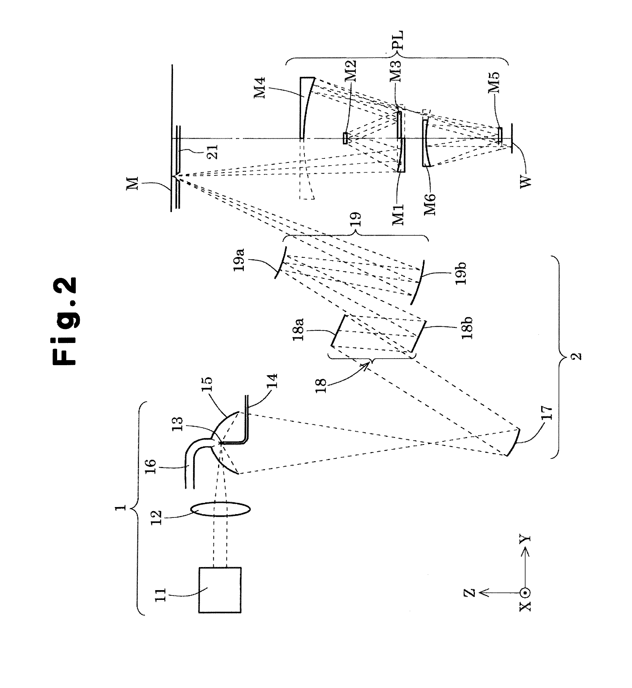
[0054]FIG. 7 is a schematic diagram showing the main structure of an illumination optical system according to a first example. Referring to FIG. 7, the condenser optical system 19 forming the main part of the illumination optical system 2 of the first example is a reflection-type condenser system in which a convex reflection mirror 19a and a concave reflection mirror 19b are arranged in this order with respect to the light received from the aperture stop AS arranged substantially at the same position as the reflection plane of the second fly's eye optical system 18b. The aperture stop AS may be separated from the reflection plane of the second fly's eye optical system 18b by a certain distance. For example, the aperture stop AS may be arranged along the optical axis separated by two millimeters from a position at which the second fly's eye optical system is most projected. In this case, when the separated distance influences the functions of the aperture stop and becomes problematic...
second example
[0060]FIG. 8 is a schematic diagram showing the main structure of an illumination optical system according to a second example. Referring to FIG. 8, the condenser optical system 19 forming the main part of the illumination optical system 2 of the second example includes a concave reflection mirror 19a and a concave reflection mirror 19b, which are arranged in this order with respect to the light received from the aperture stop AS arranged substantially at the same position as the reflection plane of the second fly's eye optical system 18b. FIG. 8 shows a state in which light beam from an infinitely distant object (not shown) passes by the aperture stop AS and the second fly's eye optical system 18b and then by the concave reflection mirror 19a and the concave reflection mirror 19b to form an image on the mask M. Table (3), which is shown below, lists data values of the main part of the illumination optical system in the second example. In the lens data section of table (3), surface ...
PUM
 Abstract
Description
Claims
Application Information
 - R&D
- Intellectual Property
- Life Sciences
- Materials
- Tech Scout
- Unparalleled Data Quality
- Higher Quality Content
- 60% Fewer Hallucinations
Browse by: Latest US Patents, China's latest patents, Technical Efficacy Thesaurus, Application Domain, Technology Topic, Popular Technical Reports.
© 2025 PatSnap. All rights reserved.Legal|Privacy policy|Modern Slavery Act Transparency Statement|Sitemap|About US| Contact US: help@patsnap.com


