Eureka AIR delivers breakthrough ideas for toughest innovation challenges, trusted by R&D personnel around the world.

Hydraulic Isolating Manifold

a technology of isolating manifolds and manifolds, which is applied in the direction of hose connections, couplings, fluid couplings, etc., can solve the problems of high-speed fluid penetration or cutting into objects or exposed skin, the valve itself is ejected from the manifold at a high speed, and the difficulty of servicing known hydraulically actuated control systems, etc., to achieve the effect of reducing or eliminating the possibility of a technician or other equipmen

Active Publication Date: 2009-02-12
EMERSON PROCESS MANAGEMENT POWER & WATER SOLUTIONS
View PDF14 Cites 0 Cited by
  • Summary
  • Abstract
  • Description
  • Claims
  • Application Information

AI Technical Summary

Benefits of technology

[0007]Thus, the isolating manifold described herein enables a valve or other component to be removed from a hydraulic manifold of a hydraulically actuated control system without requiring the control system to be shut down and without requiring the operator or technician to manually run block and bleed procedures with respect to the component being removed. This isolating manifold thereby provides for safe and efficient removal of a component from a hydraulic control manifold because the isolating manifold operates automatically to isolate the component (using the proper block and bleed procedures) from the fluid lines of the hydraulic control manifold as the component is removed from the hydraulic manifold. As a result, use of the isolating manifold described herein substantially reduces or eliminates the possibility of a technician or of other equipment being harmed by the release of highly pressured hydraulic fluid during the removal process. In a similar manner, use of the isolating manifold described herein allows a component, such as a valve, to be connected to a hydraulic control manifold while the hydraulic control manifold is in use, and without running any separate procedures on the component or the control manifold to enable the assembly to occur.

Problems solved by technology

While using these configurations is generally not a problem, it can sometimes be difficult to service known hydraulically actuated control systems, especially when such systems have a large number of valves or other components attached to a hydraulic manifold.
Only after blocking and bleeding the valve or other component, is it safe to begin to remove the valve or other component from the hydraulic manifold as removal of a valve or other component having highly pressurized fluid therein, or while this component is exposed to an unblocked high pressure line of the hydraulic manifold, can result in highly pressurized fluid squirting out of the valve or manifold during the removal process, which can result in high velocity fluid penetrating or cutting into objects or exposed skin, and can even cause the valve itself to be ejected away from the manifold at a high velocity.
Both of these conditions result in serious safety hazards to personnel as well as a potential cause of damage to the control system hardware.
In many instances, it is extremely undesirable and sometimes very expensive to halt the operation of the control system each time there is a need to perform service on some component of the system.
In many cases, these block and bleed procedures are hard to implement or may be complex to perform, resulting in the possibility that the technician incorrectly performs these procedures.
Thus, in many cases, the technician may fail to properly isolate the component being removed from the hydraulic manifold because of these difficulties.
Still further, in these systems, it is difficult to tell, by looking at the outside of the hydraulic manifold, if the valve or other component to be serviced has been properly isolated from the manifold, and thus there is no easy way to determine if the appropriate block and bleed procedures have been performed for the component being removed or if, instead, the component is still exposed to a high pressure fluid line.
Moreover, these systems require separately controllable valves (or other components) which are used to perform the blocking and bleeding operations on the components being serviced, which results in a large, complex design having separate parts that may be expensive to manufacture and hard to implement.

Method used


Image

  • Hydraulic Isolating Manifold
  • Hydraulic Isolating Manifold
  • Hydraulic Isolating Manifold

Examples


Embodiment Construction

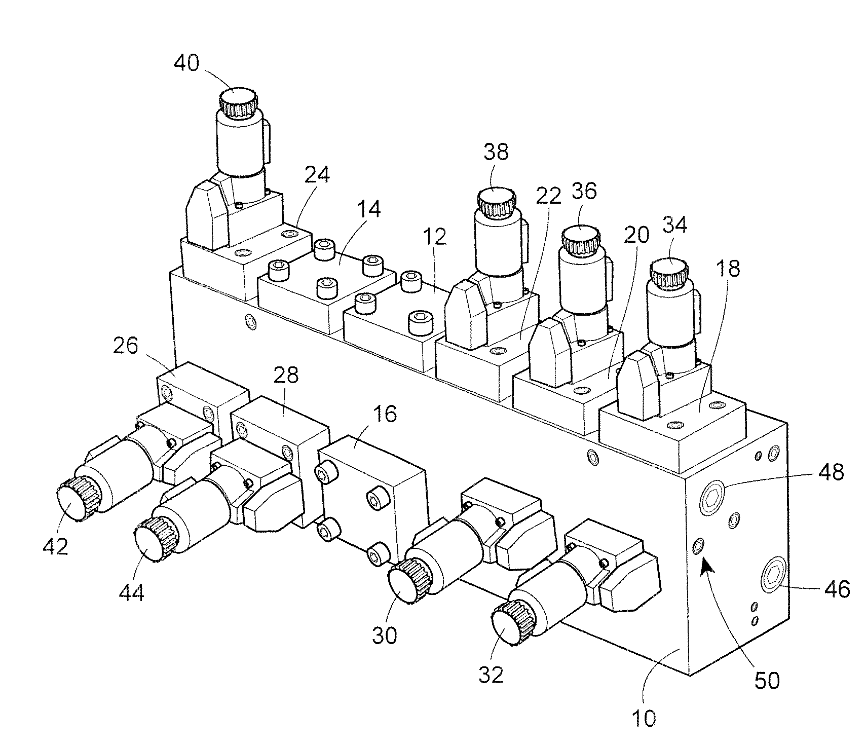
[0030]Electrically actuated, hydraulic control valves are used in many instances to control the operation of various different types of devices, such as shut-down valves, turbines or other hydraulically controlled devices within a plant environment. Such control valves, for example, are commonly used in power generating plants, processing plants, manufacturing and automated plants. In such uses, the electrically actuated, hydraulic control valves are generally electrically connected to a controller, which causes the valves to actuate to control the flow of hydraulic fluid within one or more hydraulic lines, to thereby control the operation of a further device, such as a turbine, a valve or other device connected to the hydraulic fluid line within the plant. The electrically actuated, hydraulic control valves, which may be solenoid valves or other hydraulic manifold mounted valves, are generally mechanically and fluidly connected to a hydraulic control manifold, which is designed to ...


PUM


Abstract

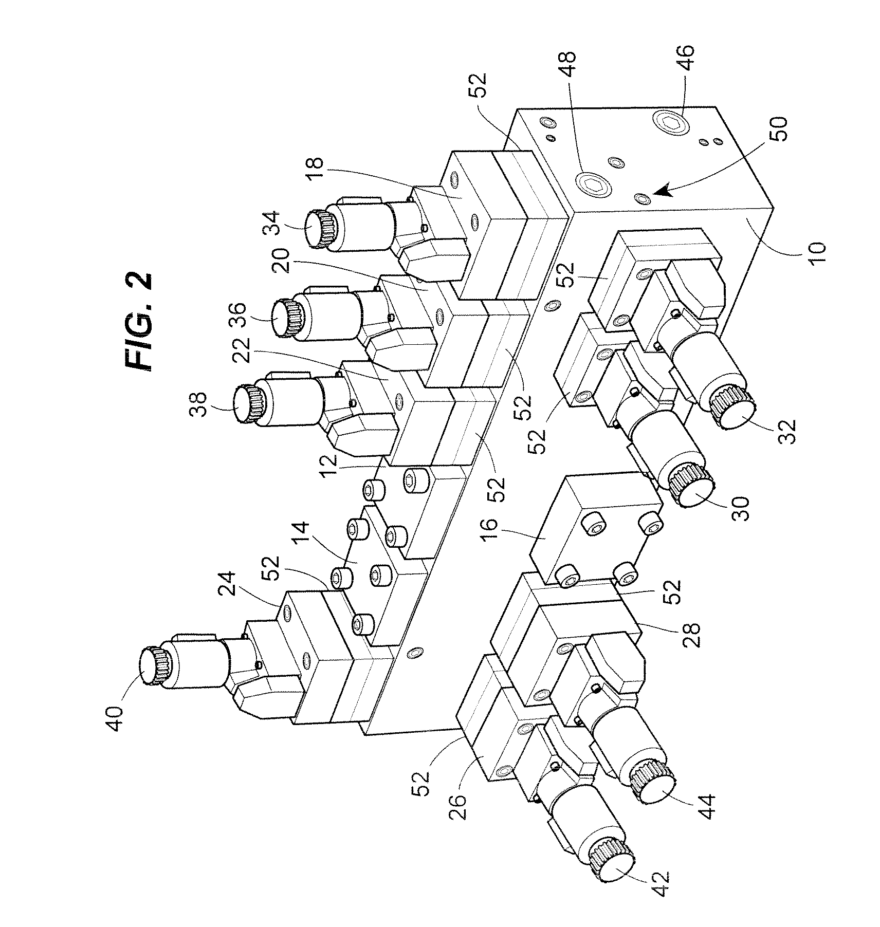
An isolating manifold fluidly connected between a hydraulic valve and a hydraulic manifold operates to automatically isolate the valve from the hydraulic manifold as the valve is removed from the manifold, without requiring any particular blocking and bleeding procedures to be implemented on the valve or the manifold prior to the removal process. The isolating manifold includes an adaptor removably mounted onto a base with various pressure, control and tank fluid channels disposed in alignment through the adaptor and base portions to allow fluid to flow through each of the channels between the hydraulic manifold and the valve. During operation, the valve is mounted onto the adaptor while the base is mounted onto the hydraulic manifold. The valve may be removed from the hydraulic manifold by removing the adaptor from the base, during which process, the isolating manifold operates automatically to block the pressure and control ports of the hydraulic manifold and to bleed pressurized fluid from the pressure and control channels of the valve to a tank channel so as to automatically isolate the valve from the hydraulic manifold as the valve is removed from the hydraulic manifold.

Description

TECHNICAL FIELD[0001]This patent relates generally to components used in hydraulic control systems and, in particular, to an isolating manifold used in a hydraulic actuated control system to automatically isolate a valve or other component from a hydraulic manifold during removal of the valve or other component from the hydraulic manifold.BACKGROUND[0002]Hydraulically actuated control systems are commonly used in many industries to control large mechanical equipment, and in one particular instance, are used to control power generation machines, such as turbines. Known hydraulically actuated control systems used in the power generation industry may, for example, include a hydraulically actuated trip control system or other protection system configured to stop the turbine (i.e., trip the turbine) upon the detection of an abnormal operating condition or other system malfunction. Typically, these hydraulically actuated control systems include a hydraulic manifold which has numerous diff...

Claims


Application Information

Patent Timeline
Patent Type & Authority Applications(United States)
IPC IPC(8): F16D31/00F16L33/00
CPCF15B13/0817F15B13/0821F16L41/03F16L29/02F16L39/00F15B13/0871F15B13/00F16L41/16Y10T137/87885F15B13/0807F15B13/0814
Inventor NATILI, JR., RICHARD PETERSINKA, STEVEN P.
Owner EMERSON PROCESS MANAGEMENT POWER & WATER SOLUTIONS
Why Eureka
Eureka Blog
Learn More