Control system for plant
a control system and plant technology, applied in the field of plant control system, can solve the problems of large size, reduced control stability, and insufficient control system to deal with the change in the dynamic characteristic of the controlled object, and achieve the effect of sufficient robustness and stability
- Summary
- Abstract
- Description
- Claims
- Application Information
AI Technical Summary
Benefits of technology
Problems solved by technology
Method used
Image
Examples
first embodiment
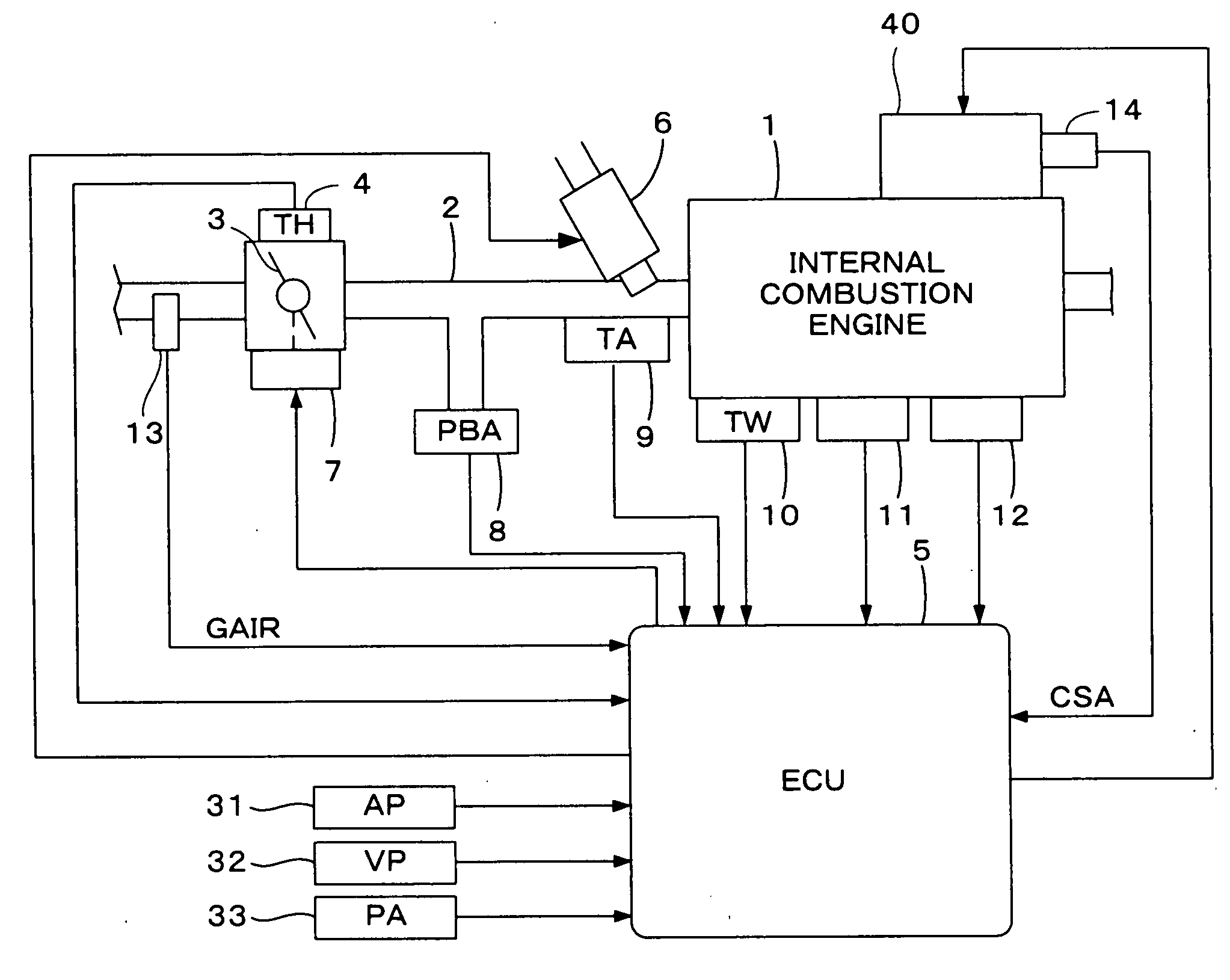
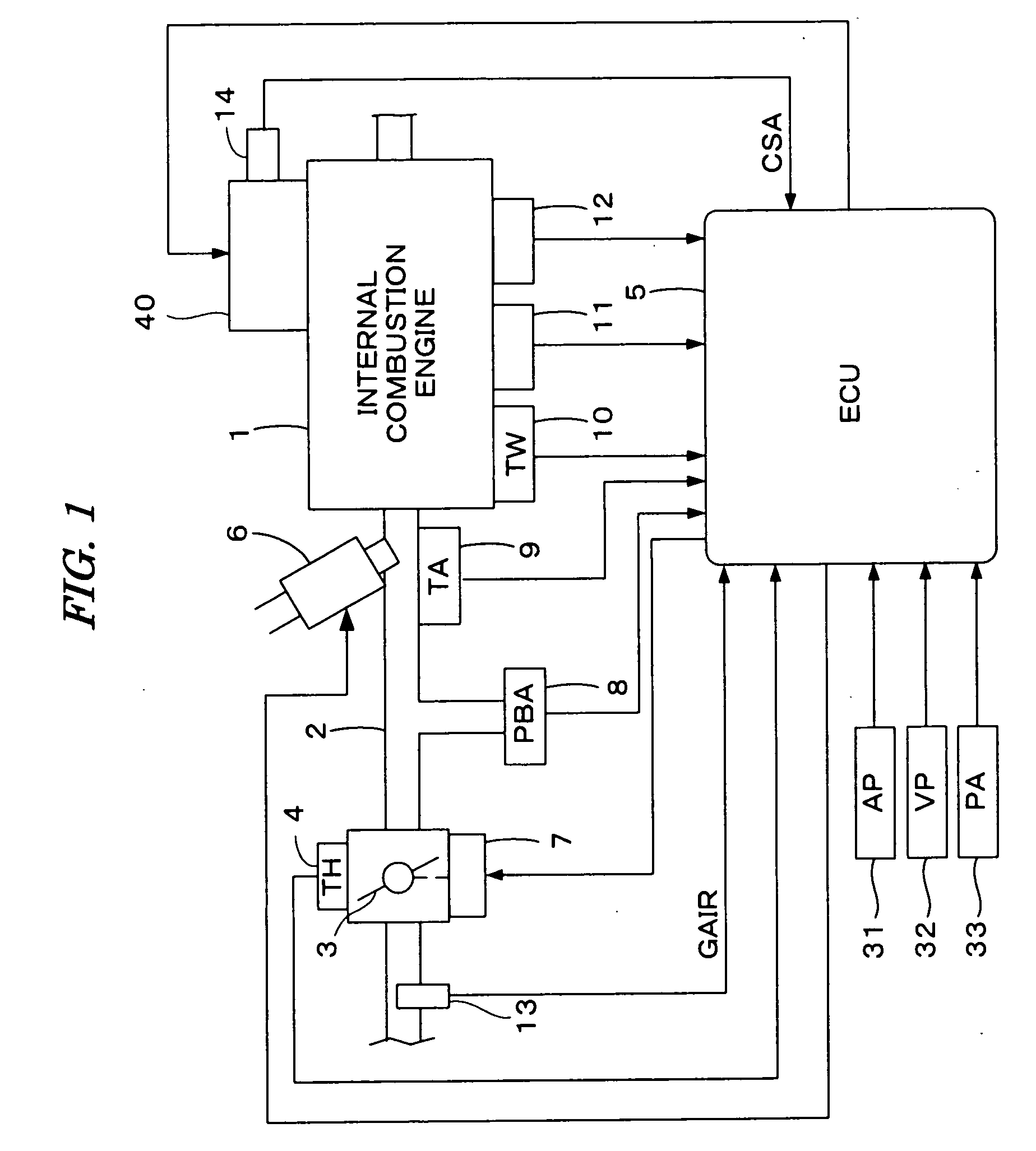
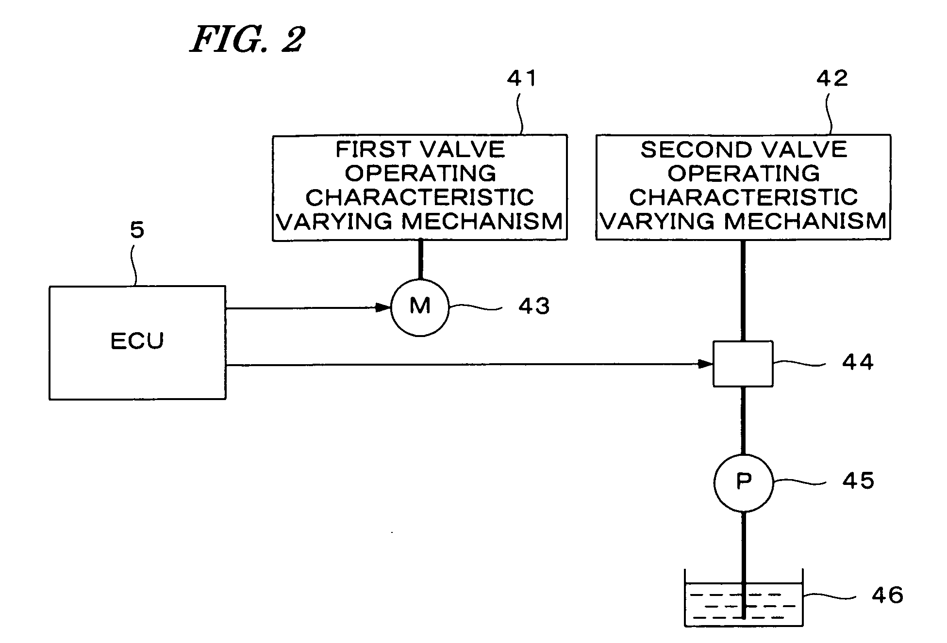
[0039]FIG. 1 is a schematic diagram showing a configuration of an internal combustion engine and a control system therefor according to a first embodiment of the present invention. FIG. 2 is a schematic diagram showing a configuration of a valve operating characteristic varying device.
[0040]Referring to FIG. 1, an internal combustion engine (hereinafter referred to as “engine”) 1, having, for example, four cylinders can be provided with intake valves and exhaust valves, and cams for driving the intake valves and the exhaust valves. The engine 1 is provided with a valve operating characteristic varying device 40 having a first valve operating characteristic varying mechanism 41 and a second valve operating characteristic varying mechanism 42. The first valve operating characteristic varying mechanism 41 can continuously vary the valve lift amount and the opening angle or valve opening period of the intake valve. The second valve operating characteristic varying mechanism 42 is a cam ...
second embodiment
[0080]FIG. 9 is a block diagram showing a configuration of a control system according to a second embodiment of the present invention. The control system shown in FIG. 9 is obtained by deleting the subtractor 102 and the frequency shaping controller 103 of the control system shown in FIG. 5, and adding a disturbance observer 104. The sliding mode controller 101 and the controlled object 100 are the same as those in the first embodiment.
[0081]The disturbance observer 104, as shown in FIG. 10, can include a inverse transfer function block 120, low-pass filters (hereinafter referred to as “LPF”) 121 and 123, and subtractors 122 and 124.
[0082]The inverse transfer function block 120 can perform a calculation which corresponds to an inverse transfer function F−1(s) of the target transfer function F(s) with respect to the CS angle CSA, to calculate a converted control input UFMI. A first LPF121 eliminates high-frequency components in the converted control input UFMI, and outputs a filtered...
third embodiment
[0102]FIG. 12 is a block diagram showing a configuration of a control system in this embodiment. The control system shown in FIG. 12 is configured by inserting a subtractor 102, a frequency shaping controller 103a, and a disturbance observer 104 between the sliding mode controller 101 and the controlled object 100. The sliding mode controller 101 and the controlled object 100 are the same as those of the first embodiment.
[0103]The disturbance observer 104 is configured as shown in FIG. 10 similarly to the second embodiment. It is to be noted that the input parameter of the disturbance observer 104 is changed from the feedback control input USL in the second embodiment to the frequency shaping control input UFS.
[0104]The frequency shaping controller 103a can be configured similarly to the first embodiment by replacing the transfer function G(s) of the controlled object 100 in the first embodiment with the target transfer function F(s) (the composite transfer function of the disturban...
PUM
 Abstract
Description
Claims
Application Information
 - R&D
- Intellectual Property
- Life Sciences
- Materials
- Tech Scout
- Unparalleled Data Quality
- Higher Quality Content
- 60% Fewer Hallucinations
Browse by: Latest US Patents, China's latest patents, Technical Efficacy Thesaurus, Application Domain, Technology Topic, Popular Technical Reports.
© 2025 PatSnap. All rights reserved.Legal|Privacy policy|Modern Slavery Act Transparency Statement|Sitemap|About US| Contact US: help@patsnap.com


