Luminescent object comprising aligned polymers having a specific pretilt angle

a technology of aligned polymers and objects, applied in the field ofluminescent objects, can solve the problems of high investment cost, high maintenance cost, unwieldy shapes, etc., and achieve the effect of dramatically increasing the efficiency of lsc-systems

Inactive Publication Date: 2009-01-29
SIGNIFY HLDG BV
View PDF14 Cites 63 Cited by
  • Summary
  • Abstract
  • Description
  • Claims
  • Application Information

AI Technical Summary

Benefits of technology

[0006]The inventors have discovered that the efficiency of LSC-systems can be increased dramatically by employing therein an aligned polymer that contains an oriented photoluminescent material. In accordance with the present invention alignment of the polymer is used to induce the orientation of the photoluminescent material. Radiation emitted by non-aligned, isotropic photoluminescent material travels in all directions, with slight preference for an emission direction perpendicular to the LSC-system for incident illumination perpendicular to the plane of the LSC-system. In other words, a large fraction of the light is emitted outside the waveguiding mode and is not transported within the waveguide. The proper alignment of the photoluminescent material within the polymer ensures that a large fraction of the light emitted by the oriented photoluminescent material is radiated into the waveguiding mode of the LSC-system.
[0007]Thus, in case of alignment at a significant pretilt angle, radiation will be emitted at an angle that allows it to be coupled very effectively into a waveguide. In the case of alignment at a large pretilt angle α relatively large fraction of the emitted radiation will meet the luminescent object's interface with air with an angle greater than the critical angle of total reflection and remain inside the object. Consequently, the use of aligned photoluminescent material makes it possible to contain a much higher fraction of the emitted light within a LSC-system than was feasible up until now. As a result, the present invention makes it possible to increase the operating efficiency of LSC systems by more than 25%.
[0009]This luminescent object may be used to convert incident light into light of a longer wavelength. In case the emitted light is radiated at a relatively small angle relative to the surface of the object (requiring the use of a relatively high pretilt angle), the emitted light can be transported efficiently within the plane parallel to said surface to, for instance, an exit or a photovoltaic device. Thus, the present film can be applied as such, without a separate waveguide, in e.g. LSCs. In this particular case it is very advantageous to use photoluminescent materials with a large Stokes Shift and / or with little overlap between the absorption and emission spectra to avoid large light losses by re-absorption phenomena.
[0010]The luminescent object according to the invention can also advantageously be coupled optically to a (transparent) waveguide (without fluorescent dyes) as the efficiency of transfer (or in-coupling) of emitted light into the waveguide is greatly enhanced by the present invention, especially if the photoluminescent material is oriented at a pretilt angle within the range of 30-70°. The optical coupling of the present luminescent object can suitably be achieved by producing a multi-layer structure (e.g. an optical laminate or a multi-layer optical fibre) in which the luminescent object is bonded as a separate layer onto the waveguide.

Problems solved by technology

These devices have several disadvantages, including high investment cost, high maintenance cost, unwieldy shapes, and the necessity of tracking the sun as it crosses the sky: for a review of current state of the art, see Swanson, Progress in Photovoltaics: Research and Applications 8, 93 (2000).
These attempts were rather unsuccessful, especially for large transport distances because the efficiencies were low or the systems require tracking of the sun or the systems were complex and not suitable for large-scale production or combinations thereof.
At the moment, LSC-systems are not used commercially which is predominantly related to their poor efficiency.
This low overall efficiency originates from a high reabsorption of emitted light (limited Stokes Shift of the dye), from a poor efficiency of coupling light into the waveguide and from a poor efficiency in keeping the light within the waveguide.

Method used


Image

  • Luminescent object comprising aligned polymers having a specific pretilt angle
  • Luminescent object comprising aligned polymers having a specific pretilt angle
  • Luminescent object comprising aligned polymers having a specific pretilt angle

Examples


example 1

Application of a Homeotropically Aligned Photoluminescent Polymer Coating

[0145]A homeotropic dye-doped liquid crystal mixture was applied to a clean 30 mm×30 mm×1 mm glass slide. The liquid crystal mixture was prepared by mixing an ethanol solution which contained 1 wt. % Irgacure 184 (ex Ciba Chemicals) and 1 wt. % Coumarin 30 (ex Aldrich Chemicals) together with a solution containing 50 wt. % RMM77 monomer and a 50 wt. % xylene in a weight ratio of 1:1. RMM77 (Merck) is a nematic homeotropic reactive liquid crystal from which the main components are the liquid crystals RM82 and RM257 (both Merck) and a homeotropic dopant. The mixture was stirred at 80° C. for 2 hours until all ethanol was evaporated. The xylene was evaporated by applying the mixture on the preheated waveguides (80° C.) for 10 minutes. After evaporation of the xylene a wet film was created with a 24 μm Meyer rod, resulting in an approximately 10 μm thick film. The samples were UV cured (λ=365 nm) under a N2 atmosph...

example 2

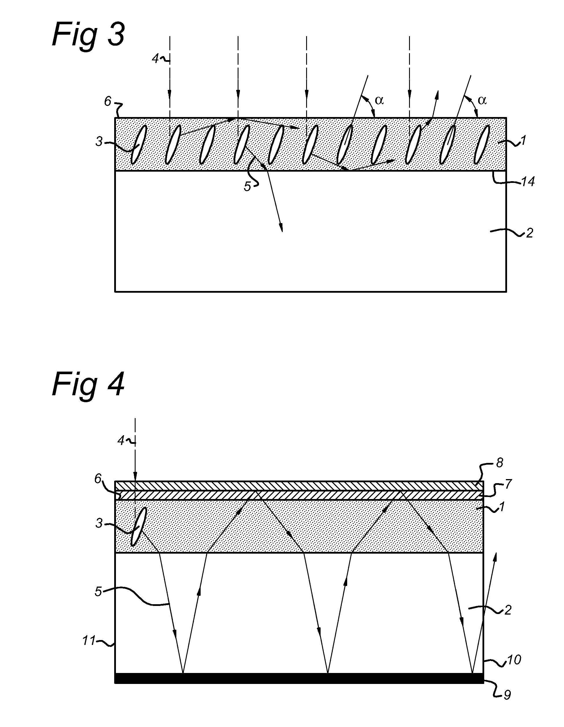
[0149]Example 1 was repeated except that first a polyimide alignment layer (Optimer A1 1051, ex JSR Micro) was spin cast onto the glass slide at 2000 rpm / s at an acceleration of 2500 rpm / S2 for 45 sec. After this the substrate was heated for 1.5 hours at 180° C. under vacuum. The alignment layer was rubbed with a velvet cloth to induce a planar alignment of the applied cholesteric liquid crystal. Next the homeotropic dye-doped liquid crystal mixture (this time using the dye DCM (4-Dicyanmethylene-2-methyl-6-(p-dimethylamino styryl)-4H-pyran (ex Aldrich Chemicals)) was applied to the opposite side of the slide as described in Example 1.

[0150]A 120 nm silver mirror was sputtered on top of the dye layer using a conventional sputter coater (Emitech K575X sputter coater, at a current of 65 mA for 2.5 min).

[0151]A cholesteric mixture was made by mixing 3.9 wt. % of a right-handed chiral dopant LC756 (ex BASF), 1 wt. % Irgacure 184 (ex Ciba Chemicals), 1 wt. % surfactant and 94 wt. % react...

example 3

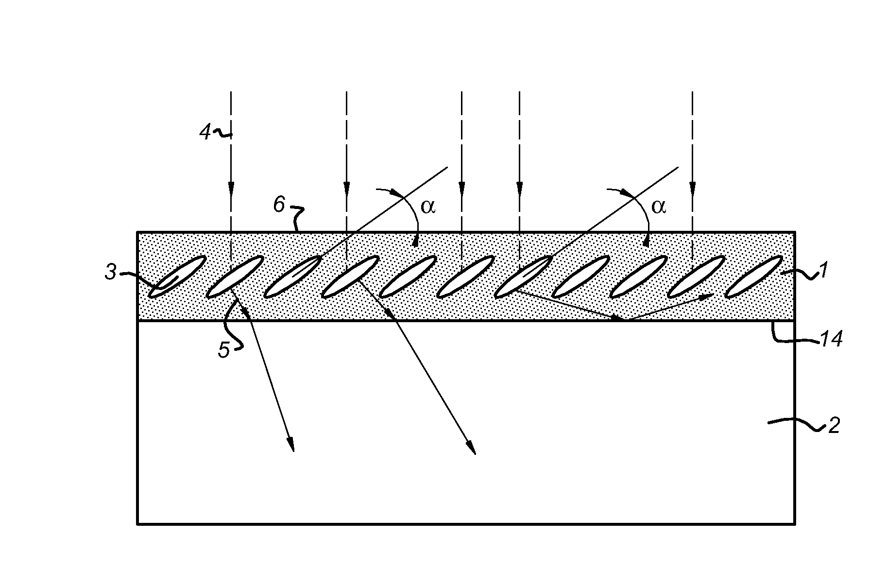
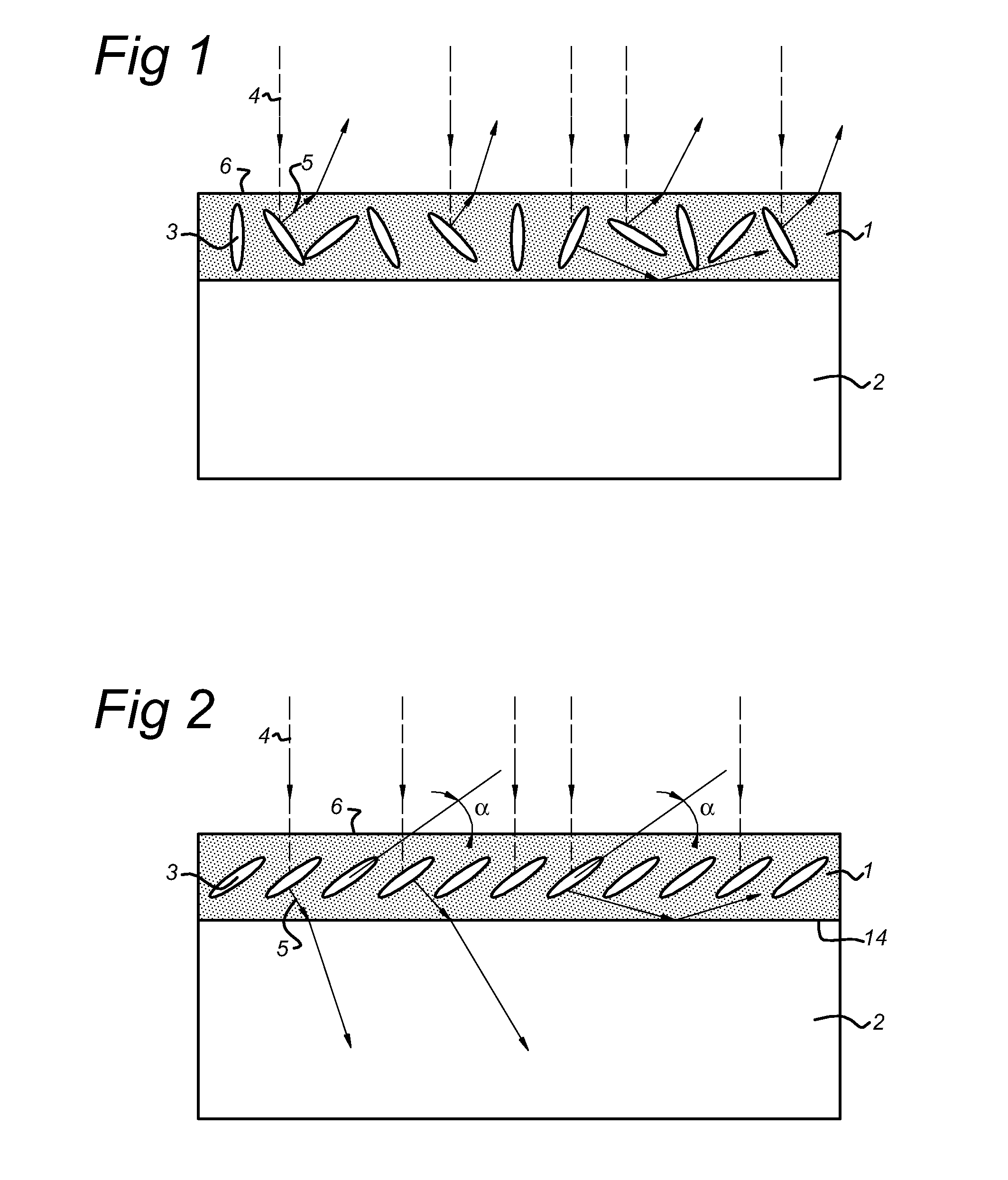
[0164]Example 1 is repeated except that a liquid crystalline polymer is employed that is aligned at a tilt angle of around 30° using the procedure described by Sinha et al in Appl. Phys. Lett. (2001), 79 (16), 2543-2545.

[0165]Again the efficiency of the LSC is measured using the methodology described in Example 1. The results show that the efficiency of the LSC exceeds the efficiency of the LSCs described in example 1. This superior efficiency is believed to be associated with an improved incoupling of the emitted radiation into the waveguide.


PUM


Abstract

A first aspect of the invention relates to a luminescent object comprising an aligned polymer that contains an oriented photoluminescent material, said aligned polymer having a pretilt angle of 10-90°. The luminescent object according to the present invention may advantageously be employed in luminescent solar concentrator systems as it enables highly efficient transportation of radiation emitted by the photoluminescent material following exposure to incident solar light. Another aspect of the invention concerns a photovoltaic device comprising an electromagnetic radiation collection medium containing the aforementioned luminescent object and a photovoltaic cell capable of converting optical radiation to electrical energy which is optically coupled to the luminescent object. Further aspects of the invention include a fluorescent light activated display and a room lighting system comprising the aforementioned luminescent object.

Description

TECHNICAL FIELD OF THE INVENTION[0001]The present invention relates to a luminescent object and in particular to the application of such a luminescent object in optical luminescent concentrator devices, such as luminescent solar concentrator devices.BACKGROUND OF THE INVENTION[0002]The cost of solar energy per unit Watt is approximately 5-10 times higher than energy from other sources, which include coal, oil, wind, biomass and nuclear. In order to reduce the cost of solar energy generation in photovoltaic systems, it is desirable to make efficient use of the most expensive part of the system, namely the photovoltaic cell (solar cell). Conventionally, this is done by using large light-focusing solar concentrators (parabolic or trough dishes). These devices have several disadvantages, including high investment cost, high maintenance cost, unwieldy shapes, and the necessity of tracking the sun as it crosses the sky: for a review of current state of the art, see Swanson, Progress in Ph...

Claims


Application Information

Patent Timeline
IPC IPC(8): H01L31/00F21V9/16F24S23/00G02B6/00H01L31/055
CPCG02B6/001Y02E10/52H01L31/055
Inventor DEBIJE, MICHAEL G.BASTIAANSEN, CEES W. M.BROER, DICK J.ESCUTI, MICHAEL J.SANCHEZ, CARLOS
Owner SIGNIFY HLDG BV
Why Eureka
Try Eureka