Wire grid type polarization element, manufacturing method thereof, liquid crystal device, and projection type display apparatus

Inactive Publication Date: 2009-01-29
SEIKO EPSON CORP
View PDF14 Cites 33 Cited by
  • Summary
  • Abstract
  • Description
  • Claims
  • Application Information

AI Technical Summary

Benefits of technology

[0011]An advantage of some aspects of the invention is to provided a wire grid type polarization element which makes it possible to improve both of “transmittance” and “contrast”, a manufacturing method thereof, a liquid crystal device equipped with the wire grid type polarization element, and a projection type display apparatus equipped with the liquid crystal device.
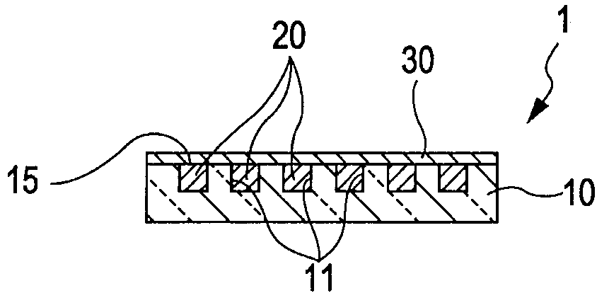
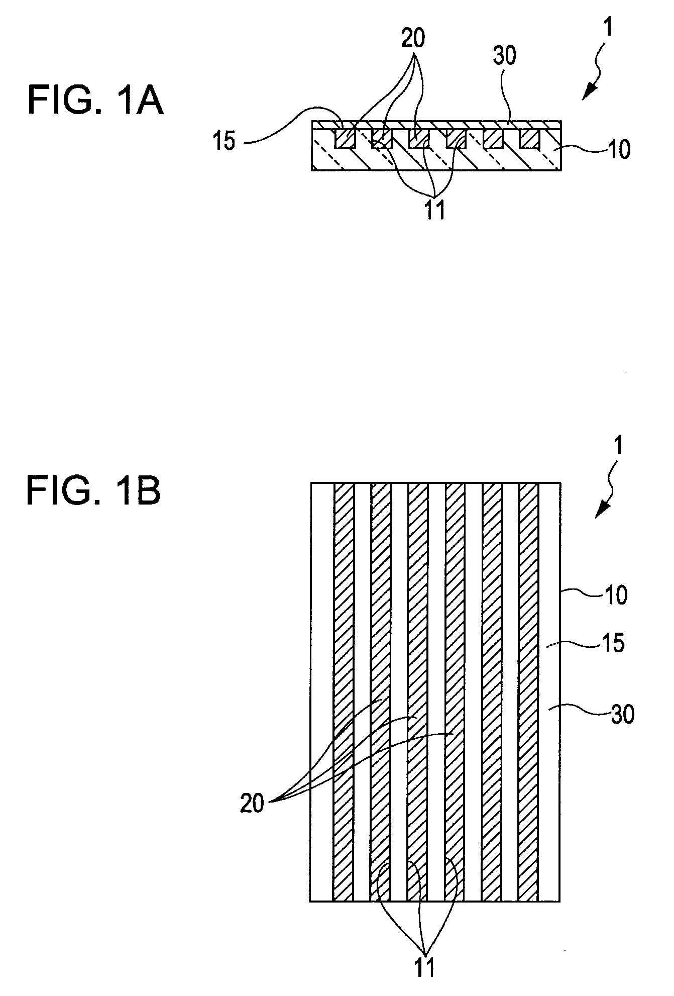
[0014]In the first and second aspects of the invention, a plurality of lines of groove concave portions are formed on the substrate surface of the translucent substrate and the metal grid is embedded in the plurality of lines of groove like concave portions. Accordingly, it is not necessary to form the metal grid by etching a metal film. Consequently, the wide size and the pitch of the metal grid are regulated by the width size and the pitch of the groove like concave portions formed on the substrate surface of the translucent substrate and are not influenced by the etching accuracy to the metal film. Consequently, the width size of the metal grid can be reduced to not more than 70 nm, for example, to 35 nm, and the pitch of the metal grid can be reduced to not less than 140 nm, for example, to 70 nm. Further, the thickness size of the metal grid is regulated by the depth of the groove like concave portions formed on the substrate surface of the translucent substrate and is not influenced by the accuracy of the film thickness when the metal film is formed. Consequently it is also possible that the ratio of the thickness size and the width size of the metal grid can be precisely set to, for example, 1:1. Consequently, both of “transmittance” and “contrast” of the wire grid type polarization element can be improved.
[0016]It is preferable that a translucent protecting layer is formed on the substrate surface in the first aspect of the invention. In the wire grid type polarization element to which the invention is applied, the metal grid is embedded in the plurality of lines of groove like concave portions formed on the substrate surface. Accordingly, the substrate surface is smooth. Consequently, a translucent protecting layer can be easily formed on the substrate surface to have an even thickness.
[0017]It is preferable that a reflection preventing layer is formed on at least one of both surfaces of the translucent substrate in the first aspect of the invention. The formation of the reflection preventing layer can improve “transmittance” of the wire grid type polarization element as reflectance loss can be reduced.
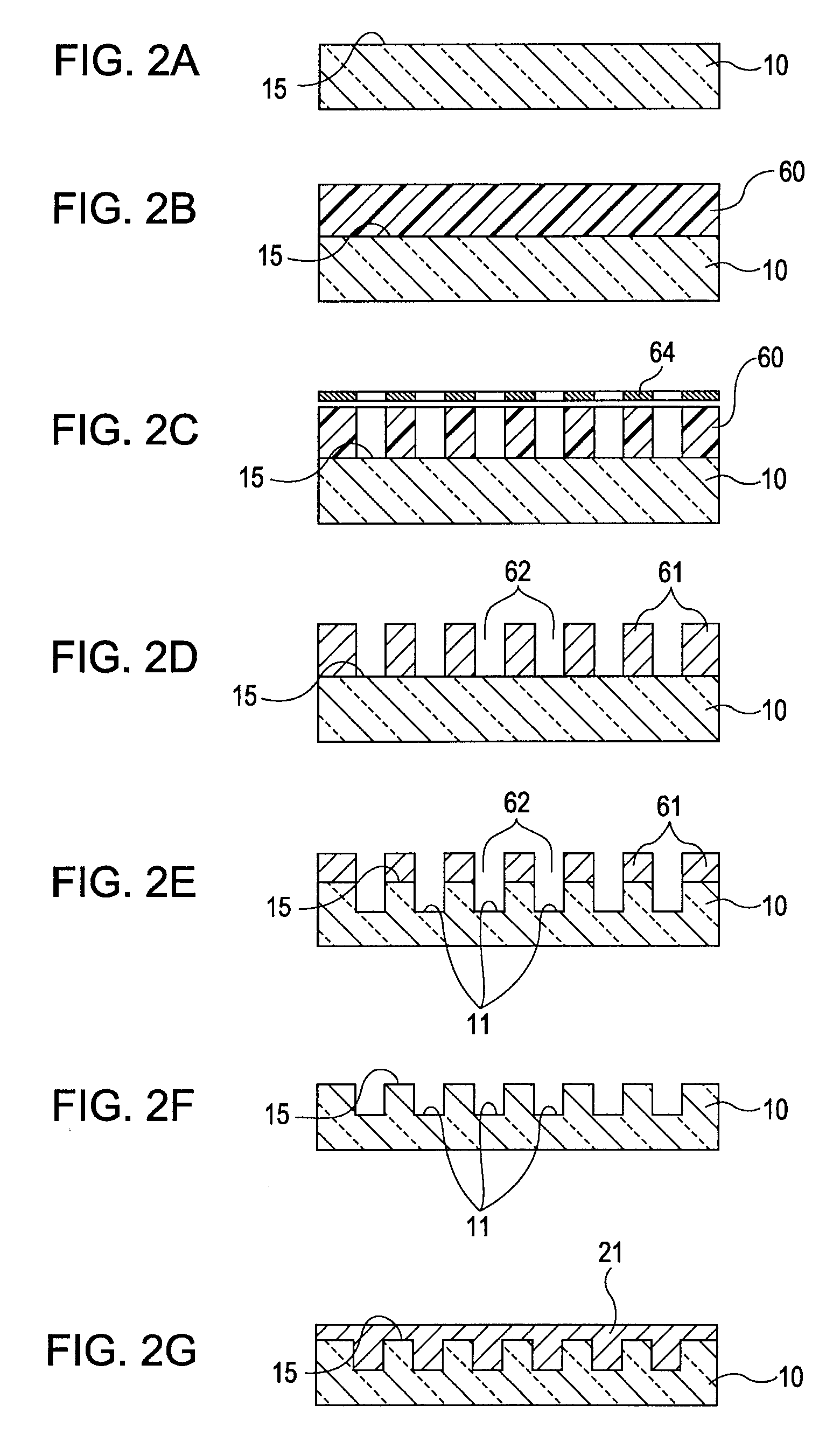
[0019]In the manufacturing method of a wire grid type polarization element according to the second aspect of the invention, it is also preferable that a mask material layer is formed on the substrate surface, and thereafter a die surface of a mold member equipped with projections at portions corresponding to the groove like openings is pressed to the mask material layer to transfer a formation pattern of the projections to the mask material layer, thereby forming the etching mask in which thicknesses of the groove like portions are reduced. According to the method, the etching mask can be formed without excessive labor hour and an expensive device for exposure, development, or the like.
[0022]In the invention, a structure may be employed in which the three liquid crystal devices are used for the projection type display device as light bulbs corresponding to each of red (R), green (G), and blue (B). Further, a structure may be employed in which the light emitted from the light source unit is optically modulated by the liquid crystal device in which a color filter is incorporated to expansively project the optically modulated light by the projection optical system. In both of the liquid crystal devices, high transmittance can be obtained with respect to any color light of red (R), green (G), and blue (B) if the wire grid type polarization element to which the invention is applied. Accordingly, a color image having a high quality can be displayed.

Problems solved by technology

Accordingly, there are problems in that the “transmittance” is widely varied in the visible light band, and the like.
Accordingly, when liquid crystal devices using the conventional wire grid type polarization elements 1A are used for a projection type display apparatus as light bulbs respectively corresponding to light of red (R), green (G), and blue (B), there are problems in that, for example, light amount is reduced for the light of red (R), and the like.
According to the method, the etching mask can be formed without excessive labor hour and an expensive device for exposure, development, or the like.

Method used


Image

  • Wire grid type polarization element, manufacturing method thereof, liquid crystal device, and projection type display apparatus
  • Wire grid type polarization element, manufacturing method thereof, liquid crystal device, and projection type display apparatus
  • Wire grid type polarization element, manufacturing method thereof, liquid crystal device, and projection type display apparatus

Examples


Embodiment Construction

[0032]Hereinafter, an embodiment of the invention will be described. In the drawings to be referred to in the following description, a scale size is changed for every layer or every member in order to make each layer and each member recognizable in the drawings. Note that in the following description, the same reference numeral is used to dente the same element so as to make it easy to recognize the distinction with respect to the structure described with reference to FIGS. 7A and 7B.

Wire Grid Type Polarization Element to Which Invention is Supplied

Structure of Grid Type Polarization Element

[0033]FIGS. 1A and 1B are a cross sectional view and a plan view schematically showing a structure of a wire grid type polarization element to which the invention is applied.

[0034]In FIGS. 1A and 1B, a wire grid type polarization element 1 of the embodiment is equipped with a plurality of lines of metal grid 20 on a substrate surface 15 of a translucent substrate 10 made of a quartz glass, a heat...


PUM


Abstract

There is provided a wire grid type polarization element equipped with a plurality of lines of metal grid on a translucent substrate. A plurality of lines of groove like concave portions are formed on the substrate, and the metal grid is embedded in the plurality of lines of groove like concave portions.

Description

BACKGROUND[0001]1. Technical Field[0002]The present invention relates to a wire grid type polarization element, a manufacturing method thereof, a liquid crystal device, and a projection type display apparatus.[0003]2. Related Art[0004]As shown in FIGS. 7A, 7b, a wire grid type polarization element 1A is equipped with a plurality of lines of metal grid 20A on a substrate surface of a translucent substrate 10A. When a pitch (period) of the metal grid 20A is shorter than a wavelength of incident light, a polarization component that vibrates in the direction perpendicular to the longitudinal direction of the metal grid 20A is transmitted whereas a polarization component that vibrates in the direction parallel to the longitudinal direction of the metal grid 20A is reflected.[0005]In the past, the wire grid type polarization element 1A is manufactured by forming a metal film on the substrate surface of the translucent substrate 10A, and thereafter forming an etching mask that is equipped ...

Claims


Application Information

Patent Timeline
IPC IPC(8): G02B5/30B29D11/00
CPCG02B5/3058G02B5/30G02B5/18
Inventor KAWAKAMI, YASUSHI
Owner SEIKO EPSON CORP
Why Eureka
Try Eureka