
Sputtering system

a technology of sputtering system and sputtering chamber, which is applied in the direction of vacuum evaporation coating, electrolysis components, coatings, etc., can solve the problems of difficult to uniformly distribute the spatial density of the plasma between the central part and the outer peripheral part of the target, and the ion collision is difficult to make the spatial density distribution of the plasma uniform, so as to facilitate the uniform thickness of the thin film formed on the substrate, facilitate the time variation of the magnetic field generated

Inactive Publication Date: 2009-01-29
TOHOKU SEIKI IND
View PDF12 Cites 23 Cited by
  • Summary
  • Abstract
  • Description
  • Claims
  • Application Information

AI Technical Summary

Benefits of technology

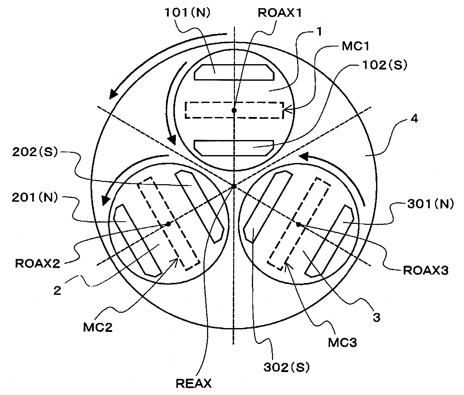
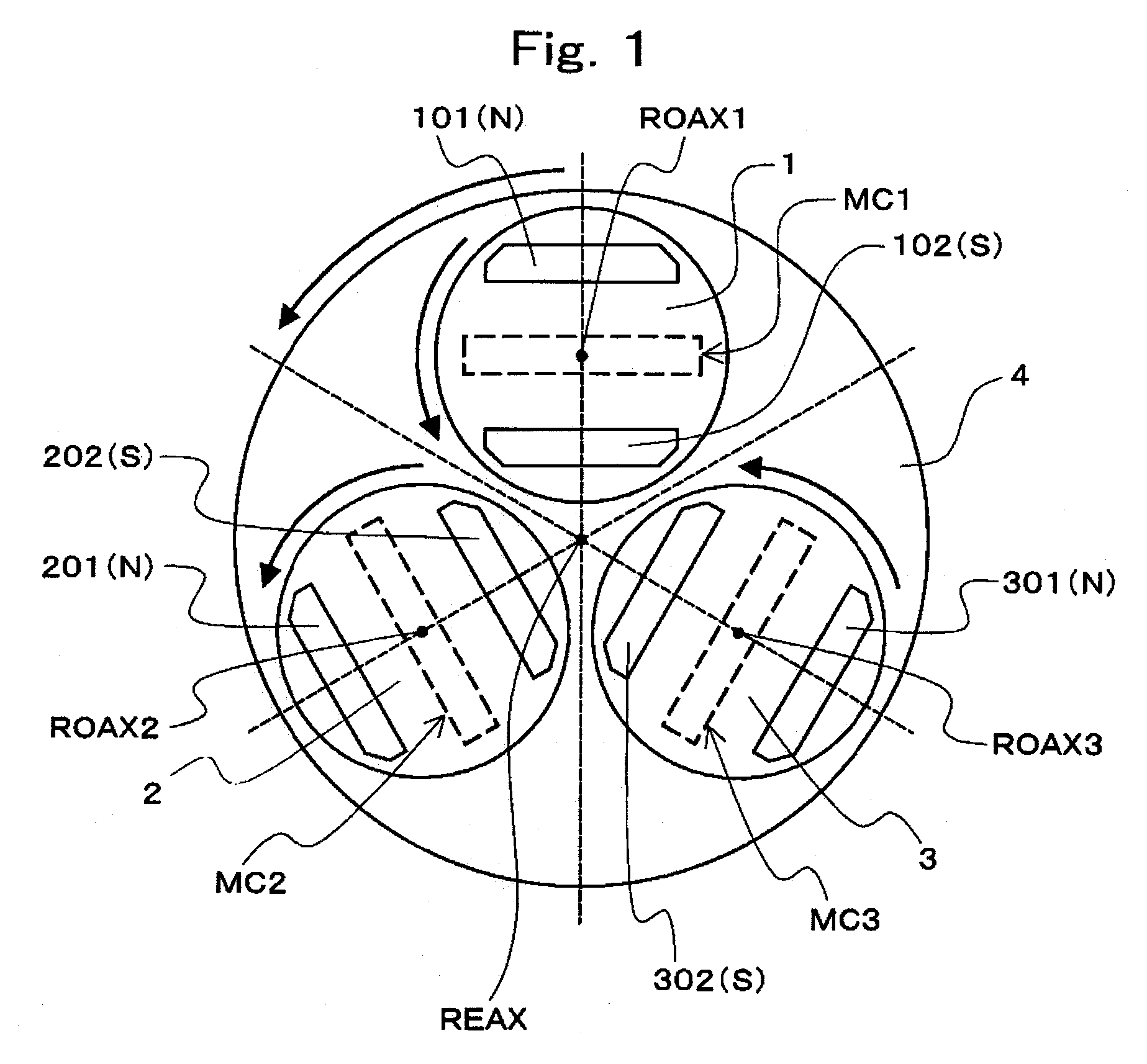
[0016]In the sputtering system according to the present invention, the magnetic field generated by each of the plurality of magnets is revolved about the axis of rotation of the magnet supporting means by revolving the plurality of magnets. At this time, when a region where the magnetic field generated by the each magnet is orthogonal to the electric field exists, the region where the magnetic field (line of magnetic force) at a moment is orthogonal to the electric field exists at a plurality of positions on the target, which makes it possible to efficiently perform sputtering. Further, at this time, the regions where the magnetic field generated by the each magnet is orthogonal to the electric field are changed in a complicated manner by revolving and rotating the respective magnets, which reduces the deviation of the regions (erosion regions) where many atoms or molecules are discharged. Further, in addition to the magnetic fields generated by the respective magnets, a magnetic field is irregularly generated and extinguished between the adjacent magnets by revolving and rotating the plurality of magnets. That is, according to the sputtering system of the present invention, it is possible to facilitate the uniformization of the ion collision on the target surface and the uniformization of the spatial density distribution of the plasma, and to facilitate the homogenization and the film thickness uniformization of the thin film formed on the substrate.
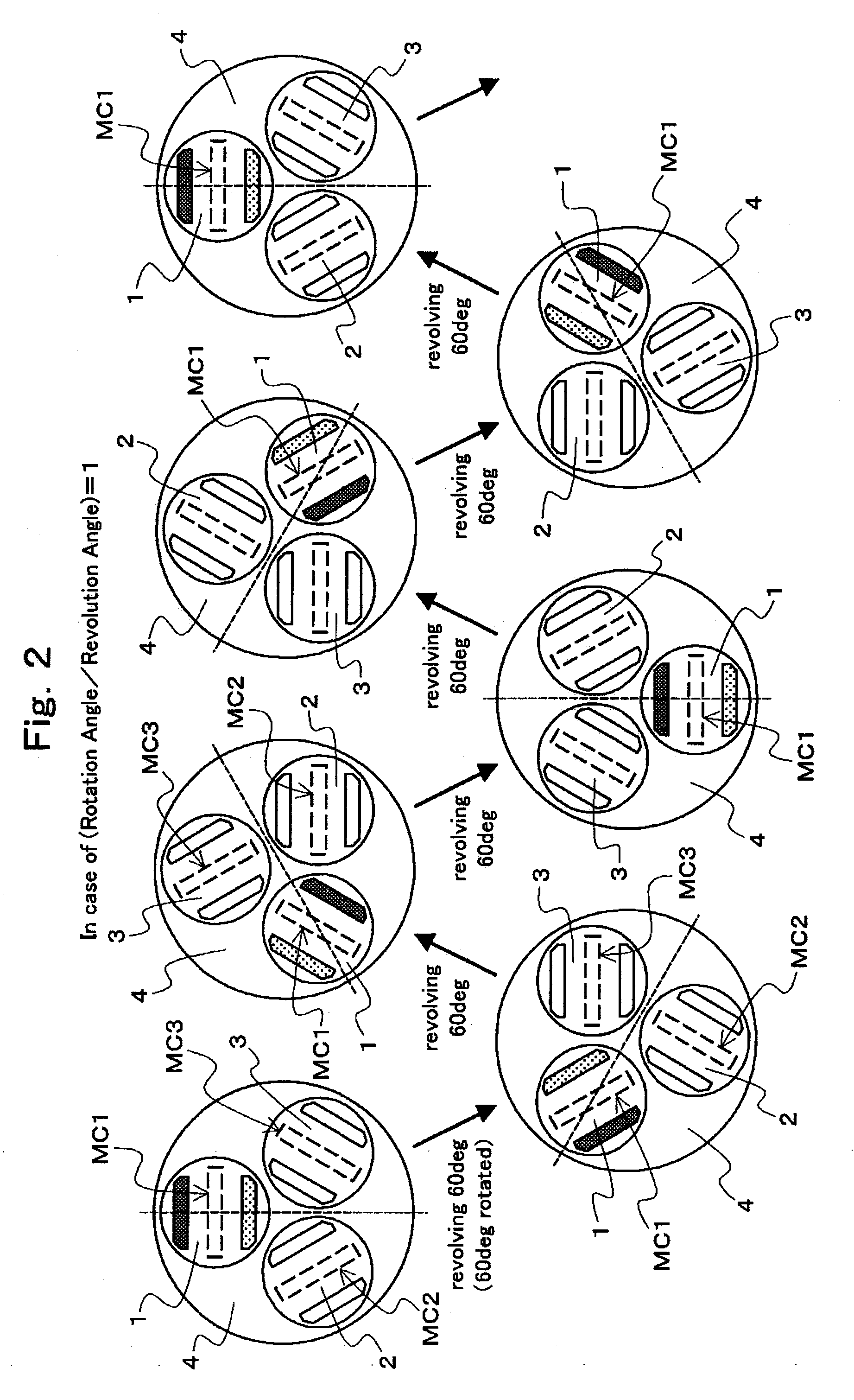
[0018]Further, in the sputtering system according to the present invention, when a gear ratio of the internal gear and the idle gear which is in mesh with the internal gear and rotates the magnet rotation gear is set to 1:R, it is preferred that R is set to not less than 1 and not more than 5, and is not a common divisor of 360. In this manner, when the each magnet revolves one time (360 degrees), the relative positional relation (angle) between the magnets before and after the revolution is different. Thereby, the time variation of the magnetic field generated by the each magnet is made still more complicated, and the ion collision on the target surface and the spatial density distribution of the plasma are made more uniform, as a result of which the homogenization and the film thickness uniformization of the thin film formed on the substrate are facilitated.
[0019]Further, in the sputtering system according to the present invention, it is preferred that the distances from the axis of rotation of the magnet supporting means to the axes of rotation of the respective magnets are made different from each other. In this manner, when the each magnet is revolved and rotated, it is possible to make the regions where the magnetic field generated by the each magnet is orthogonal to the electric field hardly overlap with each other, and to further uniformize the ion collision on the target surface and the spatial density distribution of the plasma. Thereby, the homogenization and the film thickness uniformization of the thin film formed on the substrate are facilitated.

Problems solved by technology

However, the present inventors considers that even in these methods, for example, it is difficult to make the ion collision and the spatial density distribution of the plasma uniform between the central part and the outer peripheral part of the target.

Method used


Image

  • Sputtering system
  • Sputtering system
  • Sputtering system

Examples


example

[0081]FIG. 19 to FIG. 21 are schematic diagrams showing a schematic constitution of a sputtering system of an example according to the present invention. FIG. 19 is a sectional view showing an example of an overall constitution of the apparatus. FIG. 20 is an enlarged view of the vicinity of the magnetic field applying means in FIG. 19. FIG. 21 is a figure showing a constitution example of magnet rotating means of the magnetic field applying means.

[0082]As shown in FIG. 19 and FIG. 20, a sputtering system of the present example is a system including, in a vacuum container 5 whose inside can be evacuated to a vacuum state, a substrate holder 7 adapted to hold a substrate 6 on which a thin film is formed, a target 8 provided at a position facing the thin film forming surface of the substrate 6 held by the substrate holder 7, electric field applying means (not shown) adapted to apply an electric field between the substrate 6 held by the substrate holder 7 and the target 8, and magnetic...


PUM

PropertyMeasurementUnit
electric fieldaaaaaaaaaa
magnetic fieldaaaaaaaaaa
speedaaaaaaaaaa

Abstract

A plurality of magnets are rotatably supported and when a ratio between revolution angle and rotation angle per unit time is set to 1:R, R is set to a value which is not less than 1 and not more than 5, and is not a common divisor of 360, so that the time variation of regions where a magnetic field (line of magnetic force) generated by the each magnet is orthogonal to an electric field is prevented from becoming monotonous. Further, the respective magnets are arranged to make the distances between the center of rotation and the center of revolution of the respective magnets different from each other, so that the regions where the magnetic field (line of magnetic force) generated by the each magnet is orthogonal to the electric field are dispersed in the radial direction of a target.

Description

TECHNICAL FIELD[0001]The present invention relates to a sputtering system, and more particularly, to an effective technique when applied to a magnetron sputtering system which generates a high density plasma on a target by applying magnetic fields intersecting an electric field by using magnets.BACKGROUND ART[0002]Conventionally, there is a method referred to as sputtering, as a method for forming a thin film on the surface of a silicon substrate, a resin substrate, a ceramic substrate, or the like.[0003]In the sputtering, for example, in a state where a target made of a predetermined material is arranged to face the substrate in a vacuum container, a discharge gas is introduced into the vacuum container, and a plasma is generated by applying an electric field between the substrate and the target. Thereby, atoms or molecules are discharged from the target by making positive ions of the plasma collide with the target. Then, the thin film is formed by making the discharged atoms intro...

Claims


Application Information

Patent Timeline
Patent Type & Authority Applications(United States)
IPC IPC(8): C23C14/35
CPCC23C14/35H01J37/3455H01J37/3408
Inventor HARADA, KEITAROYOKOO, MASAYOSHIKAINUMA, NORIKAZUTAKANO, YOSHINOBUTANIKAWA, ISAO
Owner TOHOKU SEIKI IND
Learn More