
Tenter clip and solution casting method

Inactive Publication Date: 2009-01-22
FUJIFILM CORP
View PDF9 Cites 1 Cited by
  • Summary
  • Abstract
  • Description
  • Claims
  • Application Information

AI Technical Summary

Benefits of technology

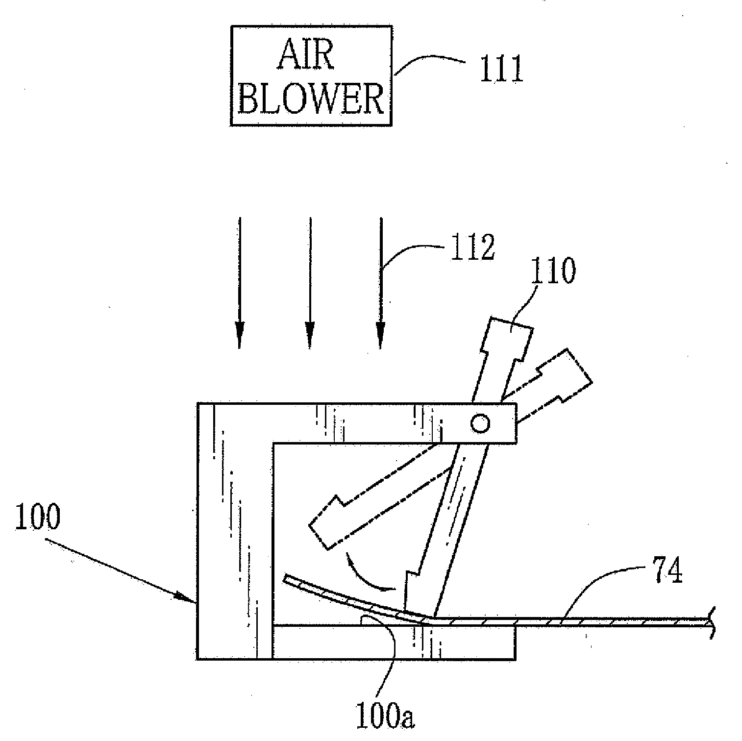
[0018]According to the tenter clip of the present invention, since a surface tension of the clipping surface being in the range of 3.0×10⁻² N / m to 3.3×10 −2 N / m, the adherence of the foreign materials and the like on a surface of the tenter clip is reduced.
[0019]Further, according to the tenter clip of the present invention, (1) surface hardness of the clipping surface is in the range of 400 Hv to 800 Hv., (2) surface roughness Ra of the clipping surface is in the range of 0.05 μm to 1 μm, and (3) a plating is made on the clipping surface. Therefore, the clipping surface is hardly scratched, and thus the adherence of the foreign materials and the like on a surface of the tenter clip is reduced more effectively.
[0020]According to the solution casting method of the present invention, since a surface tension of the clipping surface being in the range of 3.0×10⁻² N / m to 3.3×10⁻² N / m, the adherence of the foreign materials and the like on a surface of the tenter clip is reduced, and the surface defect is prevented.
[0021]Further, according to the solution casting method of the present invention, (1) surface hardness of the clipping surface is in the range of 400 Hv to 800 Hv., (2) surface roughness Ra of the clipping surface is in the range of 0.05 μm to 1 μm, and (3) a plating is made on the clipping surface. Therefore, the clipping surface is hardly scratched, and thus the adherence of the foreign materials and the like on a surface of the tenter clip is reduced more effectively, and the surface defect is prevented.
[0023]In the solution casting method, a content of solvent in the wet film at the clipping is in the range of 80 wt. % to 200 wt. % on dry basis. Thus productivity can be made higher. Further, a temperature of the tenter clip is in the range of 0° C. to 60° C. Thus the rapid evaporation of the organic solvent is reduced, and therefore the foaming is prevented. As a result, the surface conditions of the produced film are extremely excellent in surface conditions.
[0024]As a result of the consideration of the inventor, the inventor found followings. The adhesive force of the tenter clip to the wet film can be reduced by decreasing a surface energy of the clipping surface of the tenter clip. Otherwise, the increase of the surface roughness makes the contact area to the wet film smaller such that the adhesive force to the wet film may be decreased. Furthermore, if the gas concentration of the additive (such as plasticizer and the like) near the tenter clips is decreased, the precipitation of the volatile materials (such as plasticizer and the like) on the tenter clip is reduced.

Problems solved by technology

However, in this case, the pollution occurs.
In this condition, the clipping is difficult since the tenter lips just only pat the wet film and the precipitated plasticizer prevents the clipping.
Otherwise, in the clipped part, holes are formed to cause the tear of the wet film.
Further, a drying air transfers the pollution materials as foreign materials, which sometimes makes the quality of the film bad.
However, in this case, the content of the volatile materials in the wet film becomes larger.
Thus the volatile material remains on the obtained TAC film, and makes the optical properties bad.
Furthermore, if the heating device or the cleansing device is provided for the tenter clips, the tenter device has the complicated structure and becomes larger.

Method used


Image

  • Tenter clip and solution casting method
  • Tenter clip and solution casting method
  • Tenter clip and solution casting method

Examples


Embodiment Construction

[0028]In followings, embodiments of the present invention will be explained. However, the present invention is not restricted in the embodiments.

[Raw Materials]

[0029]As polymer of this embodiment, cellulose acylate is preferable, and triacetyl cellulose (TAC) is especially preferable. TAC may be produced from cotton linter or cotton pulp, or a mixture of materials respectively obtained from cotton linter and cotton pulp, and preferable TAC is produced from cotton linter. It is preferable in cellulose acylate that the degree of substitution of acyl groups for hydrogen atoms on hydroxyl groups of cellulose preferably satisfies all of following formulae (I)-(III). In these formulae (I)-(III), A is the degree of substitution of the acetyl groups for the hydrogen atoms on the hydroxyl groups of cellulose, and B is the degree of substitution of the acyl groups for the hydrogen atoms while each acyl group has carbon atoms whose number is from 3 to 22. Note that at least 90 wt. % of TAC is ...


PUM

PropertyMeasurementUnit
Temperatureaaaaaaaaaa

Abstract

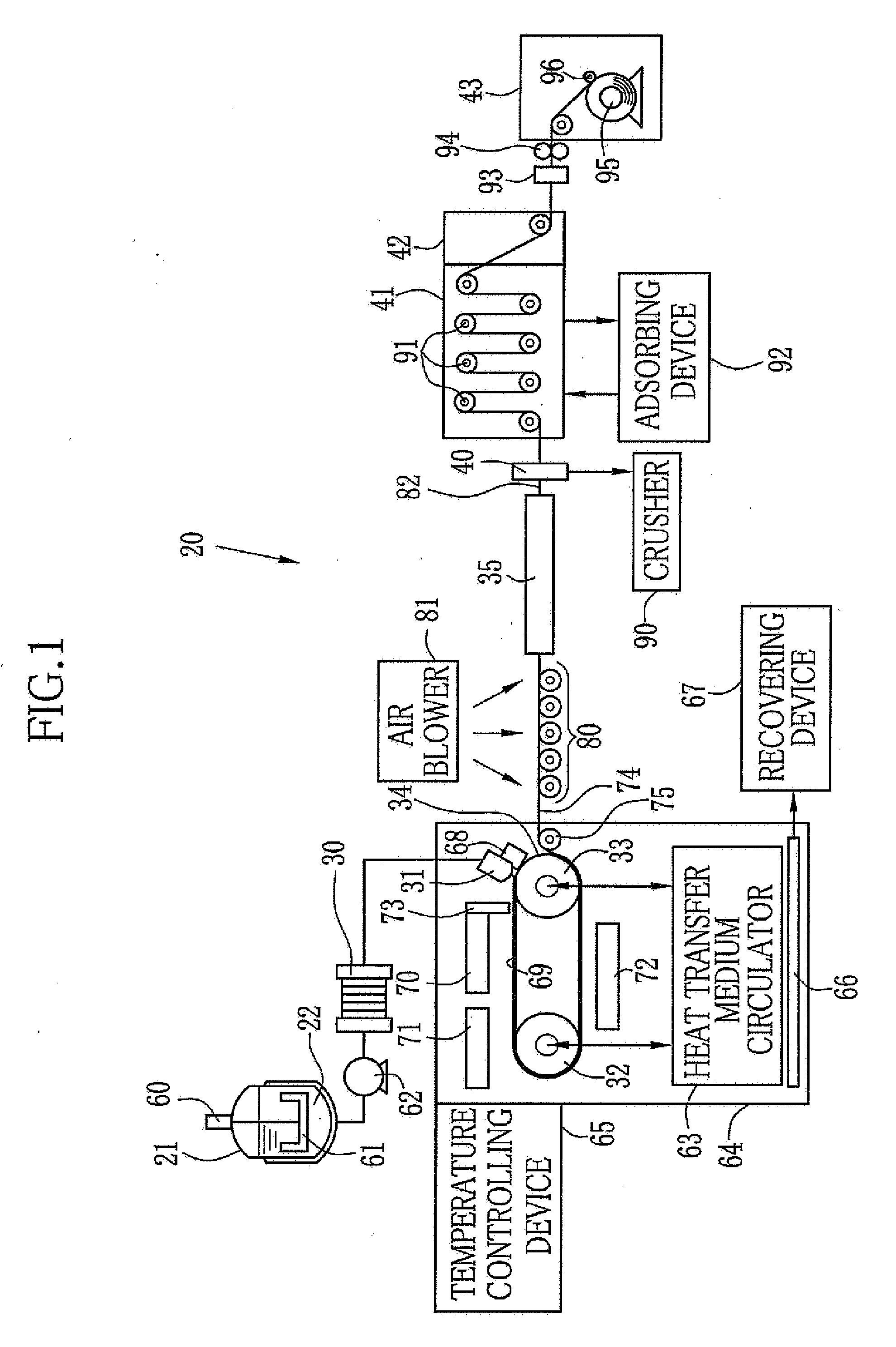
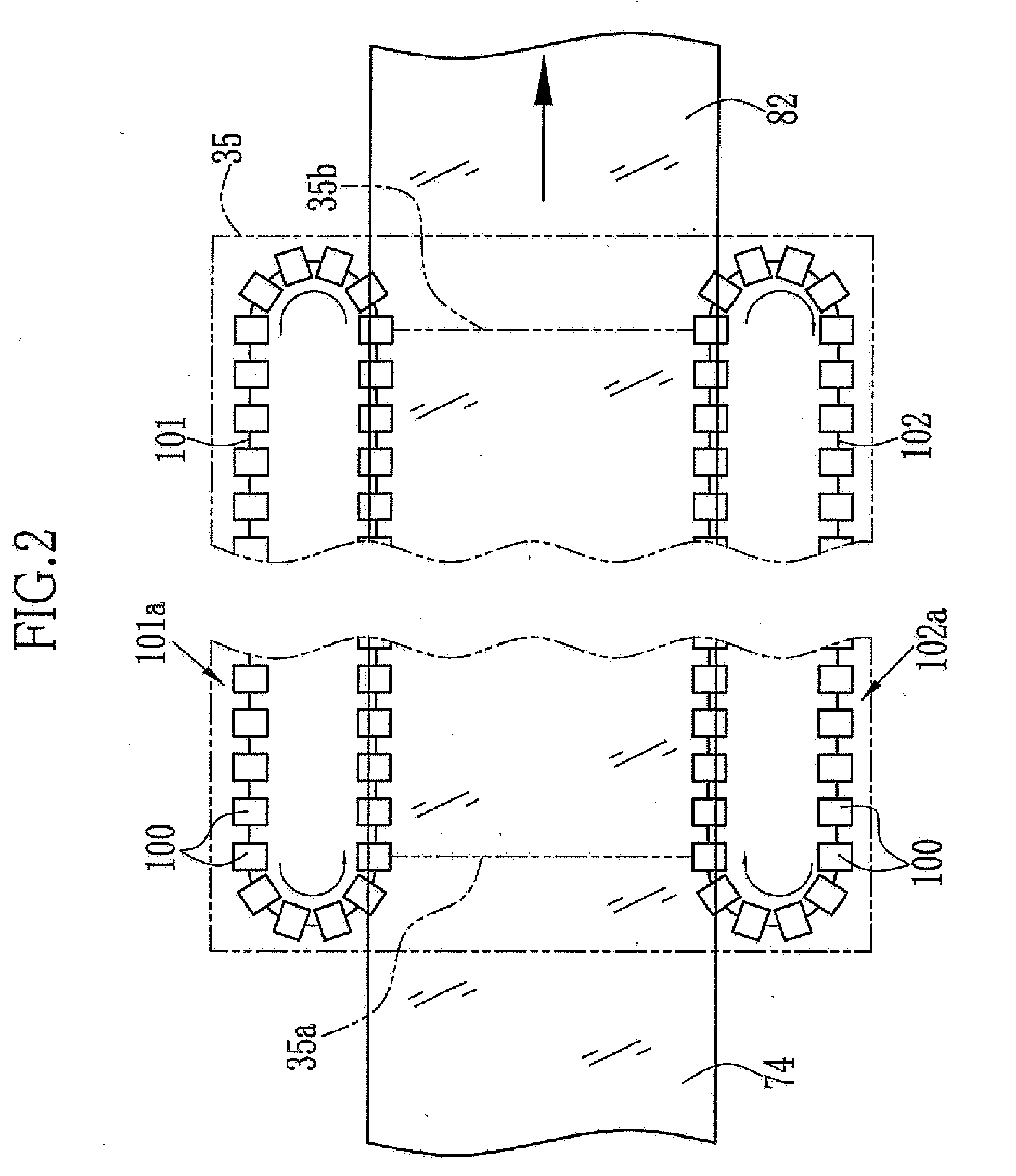
A dope is prepared from TAC, solvent and the like. The dope is cast from a casting die (31) onto a belt (34) to form a casting film (69). The casting film (69) is peeled as a wet film (74) from the belt (34). The wet film (74) is transported to a tenter device (35), in which both side edge portions are clipped by tenter clips (100). The content of the remaining solvent in the wet film 74 is determined to 100 wt. % on dry basis. The tenter clips (100) (temperature, 40° C.) has a support surface (100a) for supporting the side edge portion of the wet film 74 thereon. A surface tension of the support surface (100a) is 3.1×10⁻² N / m, a surface roughness Ra of the support surface (100a) is 0.3 μm, and a surface hardness of the holding surface (100a) is 700 Hv. Therefore, the adhesion of the foreign materials is reduced. The wet film (74) is dried with stretching in the widthwise direction by the tenter device (35), so as to obtain a TAC film (82).

Description

TECHNICAL FIELD[0001]The present invention relates to a tenter clip and a solution casting method in which a tenter device including the tenter clip is used.BACKGROUND ART[0002]A cellulose acylate film is formed from cellulose acylate. For example, especially cellulose triacetate (hereinafter TAC) film is formed from TAC whose averaged acetylation degree is in the range of 58.0% to 62.5%. The TAC film is used as a film base of a film material, such as a photosensitive material, since having strength and inflammability. Further, the TAC film is excellent in optical isotropy, and therefore used as a protective film in a liquid crystal display whose market becomes larger in recent years.[0003]The TAC film is usually produced by a solution casting method, in which the produced film is more excellent in physical properties, such as optical properties and the like, than other film production methods. For the solution casting method, polymer is dissolved to a mixture solvent in which dichl...

Claims


Application Information

Patent Timeline
IPC IPC(8): B29D7/01
CPCB29C41/28B29C55/06B65H23/028B29D7/01B29K2001/00B29C55/20B29C55/08
Inventor ARAI, TOSHINAOIKEDA, HITOSHIKOYOTA, NAOYA
Owner FUJIFILM CORP
Learn More