
Method for Producing Ceramic Honeycomb Filter

a technology of ceramic honeycomb and filter, which is applied in the field of ceramic honeycomb filter, can solve the problems of increasing engine power, reducing engine pressure loss, and reducing the ability of high exhaust gas temperature to combust pm, and reducing the elastic decrease of particulate-matter capture function

Active Publication Date: 2009-01-08
HITACHI METALS LTD
View PDF9 Cites 44 Cited by
  • Summary
  • Abstract
  • Description
  • Claims
  • Application Information

AI Technical Summary

Benefits of technology

[0012]Accordingly, an object of the present invention is to provide a method for surely forming plugs in flow paths of a ceramic honeycomb structure having large numbers of flow paths partitioned by cell walls at positions separate from the end surface in a short period of time.DISCLOSURE OF THE INVENTION
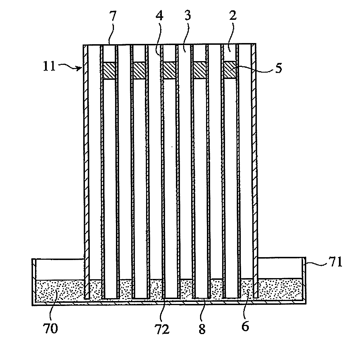
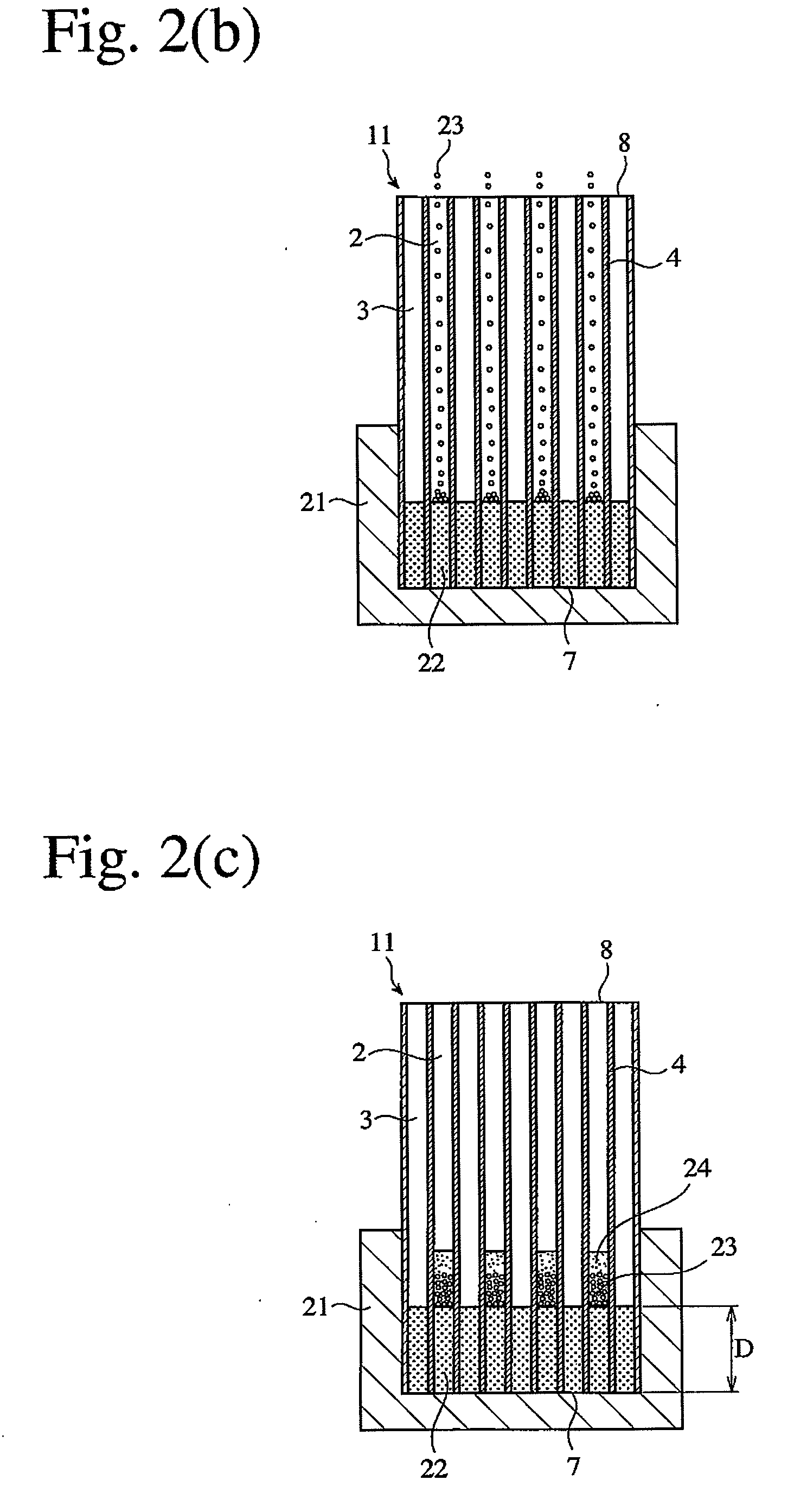
[0013]As a result of intense research in view of the above object, the inventors have found that it is possible to surely form plugs in flow paths at positions separate from the end surface in a short period of time, by introducing a base-forming material into flow paths of a ceramic honeycomb structure on one end surface side, charging a plug-forming material into flow paths to be provided with plugs from the other end surface side, and sintering it. The present invention has been completed based on such finding.
[0015]To accelerate the charging of the plug-forming material into the flow paths, the addition of a filling accelerator, and / or mechanical or ultrasonic vibration are preferable.

Problems solved by technology

As the particulate matter continues captured by the ceramic honeycomb filter 50, pores in the cell walls 3 are clogged, resulting in drastic decrease in a particulate-matter-capturing function, and increase in pressure loss that reduces engine power.
Under usual operation conditions of diesel engines, however, high exhaust gas temperatures to combust PM cannot be achieved.
In the honeycomb filter 50 having a conventional structure shown in FIG. 4, however, PM is easily attached to an inlet-side end surface 57 having low catalyst activity, particularly to end surfaces of the inlet-side plugs 55, clogging the inlet-side flow paths 2a of the filter, and thus increasing pressure loss.
However, this method produces a honeycomb filter 50 having the conventional structure shown in FIG. 4, failing to form plugs in the flow paths deep from the end surface.
However, this method cannot form plugs in flow paths deep from the end surface, and ceramic powder attached to intermediate portions of the flow paths clogs pores in cell walls, resulting in large pressure loss.
However, because it is difficult to make the expansion coefficient of the extrusion-molded honeycomb structure completely equal to that of the ceramic chips, gaps are generated between the ceramic chips and cell walls due to expansion and shrinkage by sintering, resulting in a small particulate-matter-capturing effect and insufficient bonding to the cell walls.
It has thus been found that plugs are detached, and that the ceramic chips destroy the cell walls.
In this method, however, even after the combustible powder in the first paste filling portions upstream of the inlet-side plugs is burned out, the cordierite powder is attached to the cell walls by sintering to some extent, thereby partially clogging pores in the cell walls and thus accelerating the accumulation of particulate matter.
It has been found, however, that cell walls of the flow paths are destroyed by the contacting syringe needle in this method.
Also, the paste is solidified in the syringe needle, causing clogging.
Further, because the syringe needle is inserted into individual flow paths, an extremely long period of time is needed to form plugs particularly in a large ceramic honeycomb filter having an outer diameter exceeding 150 mm, which has 10000 flow paths or more.

Method used


Image

  • Method for Producing Ceramic Honeycomb Filter
  • Method for Producing Ceramic Honeycomb Filter
  • Method for Producing Ceramic Honeycomb Filter

Examples


example 1

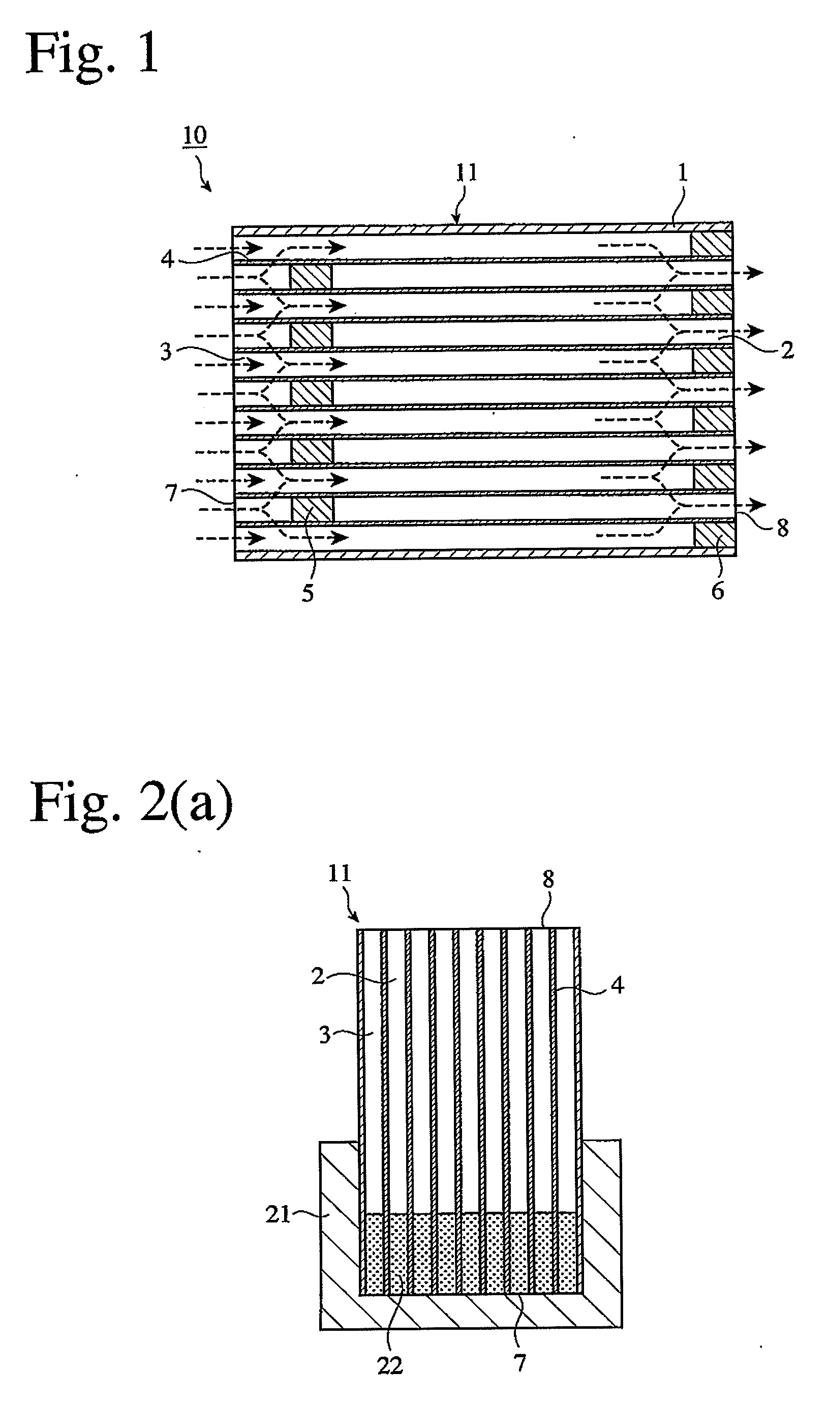
[0049]As shown in FIG. 1, a honeycomb filter 10 having large numbers of rectangular-cross-sectioned flow paths 2, 3 partitioned by cell walls 3 inside a peripheral wall 1, the end portions 7, 8 of the flow paths 2, 3 being sealed by plugs 5, 6 in a checkerboard pattern, and the plugs 5 being located in the flow paths at positions separate from the inlet-side end surface 7 was produced by the flowing steps.

[0050]Kaolin powder, talc powder, silica powder and alumina powder were mixed to provide a powdery cordierite-forming material having a composition comprising 50% by mass of SiO2, 35% by mass of Al2O3 and 15% by mass of MgO. After this powdery cordierite-forming material was mixed with methylcellulose and hydroxypropylmethylcellulose as a binder, and graphite particles as a lubricant and a pore-forming material, water was added, and full blending was conducted to produce a moldably plasticized ceramic material. This moldable ceramic material was extruded and cut to obtain a honeyco...

example 2

[0054]A cordierite honeycomb filter 10 was produced in the same manner as in Example 1, except that after changing an aqueous surfactant solution into the flow paths 2, ceramic granules were uniformly introduced while giving vibration of 100 Hz for 20 seconds to the honeycomb structure 11. By this method, plugs 5 were surely formed in the flow paths of the ceramic honeycomb structure at positions separate from the end surface in a short period of time.

example 3

[0055]A cordierite honeycomb filter 10 was produced in the same manner as in Example 1, except for using capsules (outer diameter: 1.0 mm, skin layer thickness: 100 μm) containing aqueous cordierite powder slurry as a plug-forming material in a skin layer and an oily, protective, inner layer, and heating the honeycomb structure 11 at 150° C. without using a filling accelerator to melt the capsules to permit the slurry to enter the flow paths. By this method, plugs were surely formed in the flow paths of the ceramic honeycomb structure at positions separate from the end surface in a short period of time.


PUM

PropertyMeasurementUnit
viscosityaaaaaaaaaa
outer diameteraaaaaaaaaa
particle sizeaaaaaaaaaa

Abstract

A method for producing a ceramic honeycomb filter having large numbers of flow paths partitioned by cell walls, the flow paths having plugs at positions separate from an end surface of the honeycomb filter, comprising the steps of introducing a base-forming material into the flow paths on one end surface side, charging a plug-forming material into flow paths to be provided with plugs from the other end surface side, and sintering it.

Description

FIELD OF THE INVENTION[0001]The present invention relates to a method for producing a ceramic honeycomb filter suitable for apparatuses for cleaning an exhaust gas from automobile engines, particularly apparatuses for removing particulate matter from an exhaust gas discharged from diesel engines.BACKGROUND OF THE INVENTION[0002]Used for environmental protection are honeycomb filters for removing carbon-based particulate matter from exhaust gases discharged from diesel engines. The honeycomb filter is alternately sealed on both end surfaces on the exhaust-gas-inlet and exit sides. FIG. 4 shows an example of conventional ceramic honeycomb filters having such structure. This ceramic honeycomb filter 50 is constituted by a porous ceramic honeycomb structure 11 comprising porous cell walls 3 for forming pluralities of flow paths 2a, 2b and a peripheral portion la enclosing the porous cell walls 3, plugs 55 for sealing flow paths 2b in a checkerboard pattern in an end portion of the porou...

Claims


Application Information

Patent Timeline
Patent Type & Authority Applications(United States)
IPC IPC(8): C04B33/32B06B1/20
CPCB01D46/0001C04B38/0009B01D46/2466B01D2279/30B28B11/006F01N3/0222F01N2330/30Y02T10/20B01D46/2418C04B38/0006C04B35/195C04B38/068Y02T10/12B01D39/20B01D39/00B28B11/02C04B41/00
Inventor OKAZAKI, SHUNJIOHTSUBO, YASUHIKO
Owner HITACHI METALS LTD
Learn More