
Method for producing filter molded article

a filter and molded technology, applied in the field of filter molded articles, can solve the problems of low productivity, time consumption, and the film resist supporting the graphene is broken, and achieve the effects of preventing the breakage of the support, and reducing the time consumption

Active Publication Date: 2018-05-15
KOTOBUKI HLDG CO LTD +1
View PDF41 Cites 2 Cited by
  • Summary
  • Abstract
  • Description
  • Claims
  • Application Information

AI Technical Summary

Benefits of technology

The patent is about a method for creating a filter using a graphene layer with water passage holes. The method involves heating and holding the graphene layer in air containing oxygen at a low temperature for a specific amount of time. This results in a uniform distribution of holes in the graphene without breakage or contamination. The support material, a negative photoresist, is exposed to light to form the water passage holes without causing breakage of the graphene. The method also allows for the control of the size and shape of the water passage holes in detail. Overall, the technology provides a reliable and efficient way to create filters using graphene.

Problems solved by technology

In such a conventional transfer step, a chemical or the like is consumed, time is consumed, and productivity is low.
However, in this method, a film resist supporting the graphene is broken due to heat.
In addition, control of a reaction is difficult and sizes of the water passage holes opened in the graphene are not uniform due to hole-opening by a combustion reaction of a graphite.
Therefore, this method is not suitable for a filter molded article requiring uniform water passage holes.
Furthermore, cinders of the support formed of a resin or the like generated during combustion may contaminate the graphene to lower performance of a filter molded article.

Method used


Image

  • Method for producing filter molded article
  • Method for producing filter molded article
  • Method for producing filter molded article

Examples


second embodiment

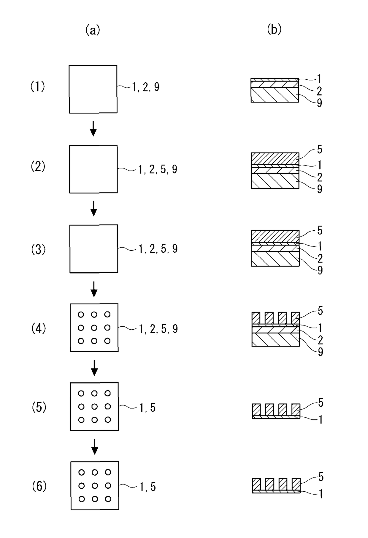
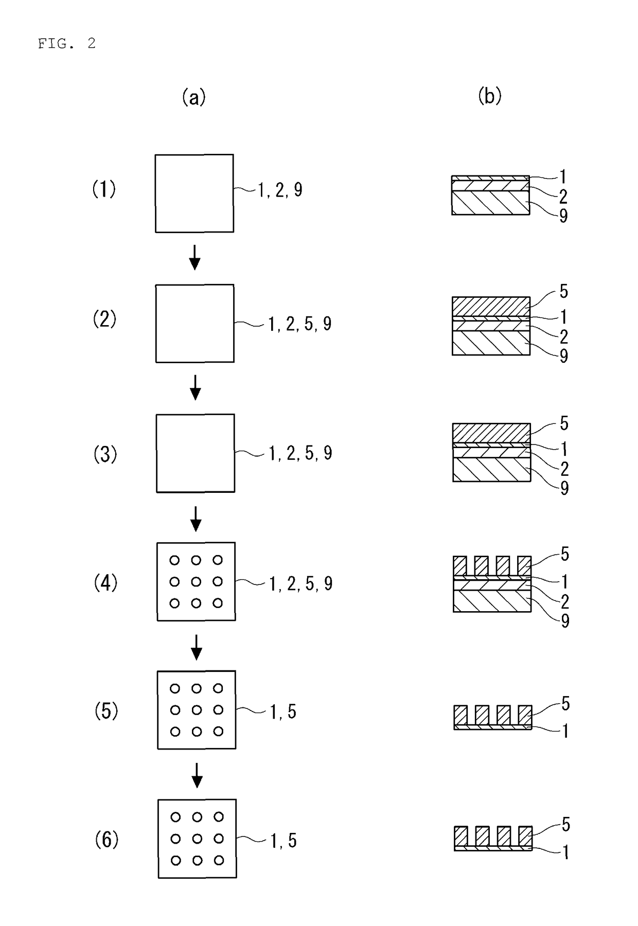
[0099]The second embodiment is characterized by forming a resist layer 5 by spin-coating a negative liquid resist on a surface of a graphene in place of using the film resist 3 formed of a negative photoresist in the first embodiment.

[0100]Also in the second embodiment, as illustrated in FIG. 2 (1), a graphene obtained by forming a copper foil 2 on a silicon substrate 9 and growing a graphene 1 on the copper foil 2 is used.

[0101]In the second embodiment, first, the resist layer 5 is formed on a surface of the graphene 1, as illustrated in FIG. 2(2).

[0102]The resist preferably has similar performance to that in the first embodiment in addition to be a liquid resist.

[0103]As such a liquid resist, an epoxy resin SU-8 3050 manufactured by Microchem Corporation is used.

[0104]The liquid resist is spin-coated on the graphene at 3000 rpm for 20 seconds using a spin coater to form a resist layer having a thickness of 50 μm.

[0105]After spin-coating, the resist layer 5 is subjected to soft bak...


PUM

PropertyMeasurementUnit
temperatureaaaaaaaaaa

Abstract

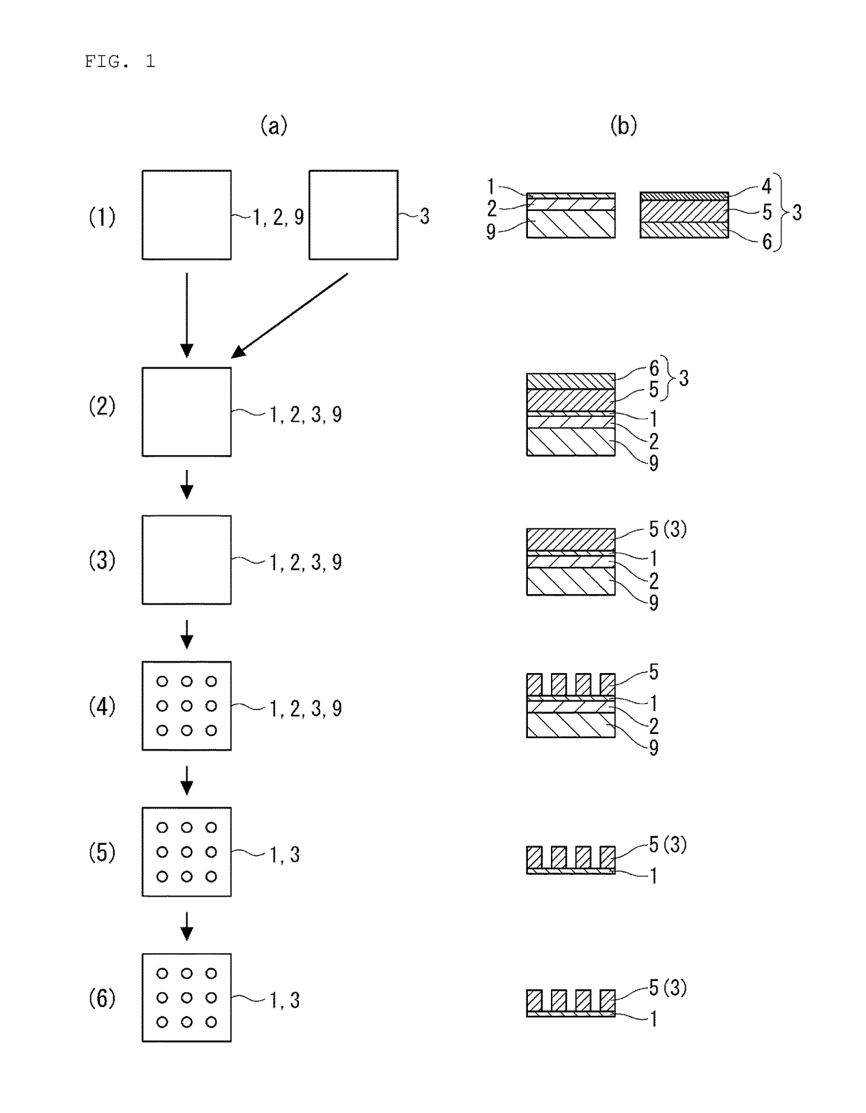
A filter molded article using a graphene with water passage holes having a desired size is produced in a simple step.A method for producing a filter molded article having a graphene layer as a filtering material is characterized by including a step of forming a support 3 layer on a surface of a graphene 1 layer formed on initial substrates for a graphene 2 and 9, a step of forming water passage holes in the support 3 layer, a step of removing the initial substrates for a graphene 2 and 9, and a step of forming water passage holes by heating and holding the graphene 1 layer at a low temperature in the air containing oxygen of 160 to 250° C. for a predetermined time.

Description

CROSS REFERENCE[0001]This application is a United States national phase application of co-pending international patent application number PCT / JP2015 / 072206, filed Aug. 5, 2015, which claims priority to Japanese patent application number 2014-163350, filed Aug. 11, 2014, the entire disclosures of which are hereby incorporated herein by reference.TECHNICAL FIELD[0002]The present invention relates to a method for producing a filter molded article, particularly to a method for producing a filter molded article having a filter using a graphene.BACKGROUND ART[0003]In recent years, as a filter for removing fine particles such as ions from water, another solution, or gas, a filter molded article employing a graphene having fine water passage holes formed has come to be used (Patent Literature 1).[0004]In general, a graphene is formed on a surface of a copper foil or the like by a chemical vapor deposition (CVD) method (Patent Literature 2). Therefore, conventionally, a step of transferring ...

Claims


Application Information

Patent Timeline
Patent Type & Authority Patents(United States)
IPC IPC(8): B01D67/00B01D69/12B01D71/02G03F7/20G03F7/40G03F7/038G03F7/16G03F7/32
CPCB01D67/006B01D69/125B01D71/021G03F7/038G03F7/2004G03F7/325G03F7/40G03F7/162B01D2323/08B01D67/0062B01D67/0079B01D2323/34C01B32/05B01D2323/081B01D2323/64B01D67/00791B01D69/1071B01D71/0211B01D69/107B01D69/1213
Inventor KANEKO, KATSUMITAKAGI, TOSHIOMURATA, KATSUYUKI
Owner KOTOBUKI HLDG CO LTD
Learn More