
Substrate processing apparatus

Inactive Publication Date: 2008-12-11
NTT MOBILE COMM NETWORK INC
View PDF5 Cites 279 Cited by
  • Summary
  • Abstract
  • Description
  • Claims
  • Application Information

AI Technical Summary

Benefits of technology

[0007]A primary object of this invention is to provide a substrate processing apparatus capable of stabilizing the supply of an evaporated gas of liquid raw material to the processing chamber.
[0009]According to this invention, the feedback device is arranged to feed back the detection result of the detector device to the flow rate control device. Thus, it is possible to recognize the actual feed amount of the evaporated gas of the liquid raw material. It is also possible to precisely control the feed rate of the inactive gas without relation to variations of a liquid surface of the liquid raw materials in the first and second liquid raw material tanks. This makes it possible to stabilize the feed rate of the evaporated gas of liquid raw material to the processing chamber. Therefore, it is possible to suppress unwanted production of particles otherwise occurring due to reliquefaction of the evaporated gas of liquid raw material and flow blockage or “clogging” at a gas feed nozzle which is provided within the processing chamber and also possible to improve uniformity of the thickness of a film to be formed on the substrate.

Problems solved by technology

In this case, it is possible to control the feed rate of the carrier gas; however, it is impossible to recognize the actual feed rate of the evaporated gas of the liquid raw material.
Thus, the above-stated apparatus still fails to directly control the feed rate of the evaporated gas of liquid raw material; so, it remains difficult to stabilize the feed rate of the evaporated gas of liquid raw material supplied to the processing chamber.
For this reason, even when the supply of the evaporated gas of liquid raw material becomes unstable in state due to some sort of causes (such as pipe clogging due to a residual by-product material), it is no longer possible to detect such state.
This can cause the evaporated gas to be liquefied again or “reliquefied” within the pipe in which the evaporated gas is flowing, resulting in production of contaminant particles.
These particles often badly behave to block or “choke” not only the pipe but also a gas supply nozzle or the like, which is provided within the processing chamber.
When its liquid surface is varied (reduced) in accordance with the use amount of the liquid raw material, it is impossible to accurately detect the temperature of the liquid surface of the liquid raw material.
At this time, even when an attempt is made to accurately control the feed rate of the carrier gas, it is not possible to increase its accuracy.
Thus, it becomes difficult to stabilize the feed rate of the evaporated gas of liquid raw material to the processing chamber also, resulting in the lack of an ability to improve uniformity of the thickness of a film to be formed on the substrate.

Method used


Image

  • Substrate processing apparatus
  • Substrate processing apparatus
  • Substrate processing apparatus

Examples


embodiment 1

[0063]Next, an explanation will be given of film fabrication examples using ALD method in regard to the case of an Al2O3 film being formed by use of TMA and O3 gases and the case of a HfO2 film being formed by using TEMAH and O3 gases, each of which cases is one of semiconductor device fabrication processes.

[0064]The ALD (Atomic Layer Deposition) method, which is one of CVD (Chemical Vapor Deposition) methods, is a technique for alternately supplying, one at a time, two (or more) kinds of raw material gases used for the film fabrication onto a wafer 200 under specified film forming conditions (temperature, time, etc.) and for causing adsorption with a one atomic layer being as a unit to thereby perform the intended film formation by utilizing surface reaction.

[0065]More specifically, in the case of forming an Al2O3 (aluminum oxide) film as an example, it is possible to form a high-quality film at low temperatures of 250 to 450° C., by alternately supplying a vaporized gas of TMA (Al...

embodiment 2

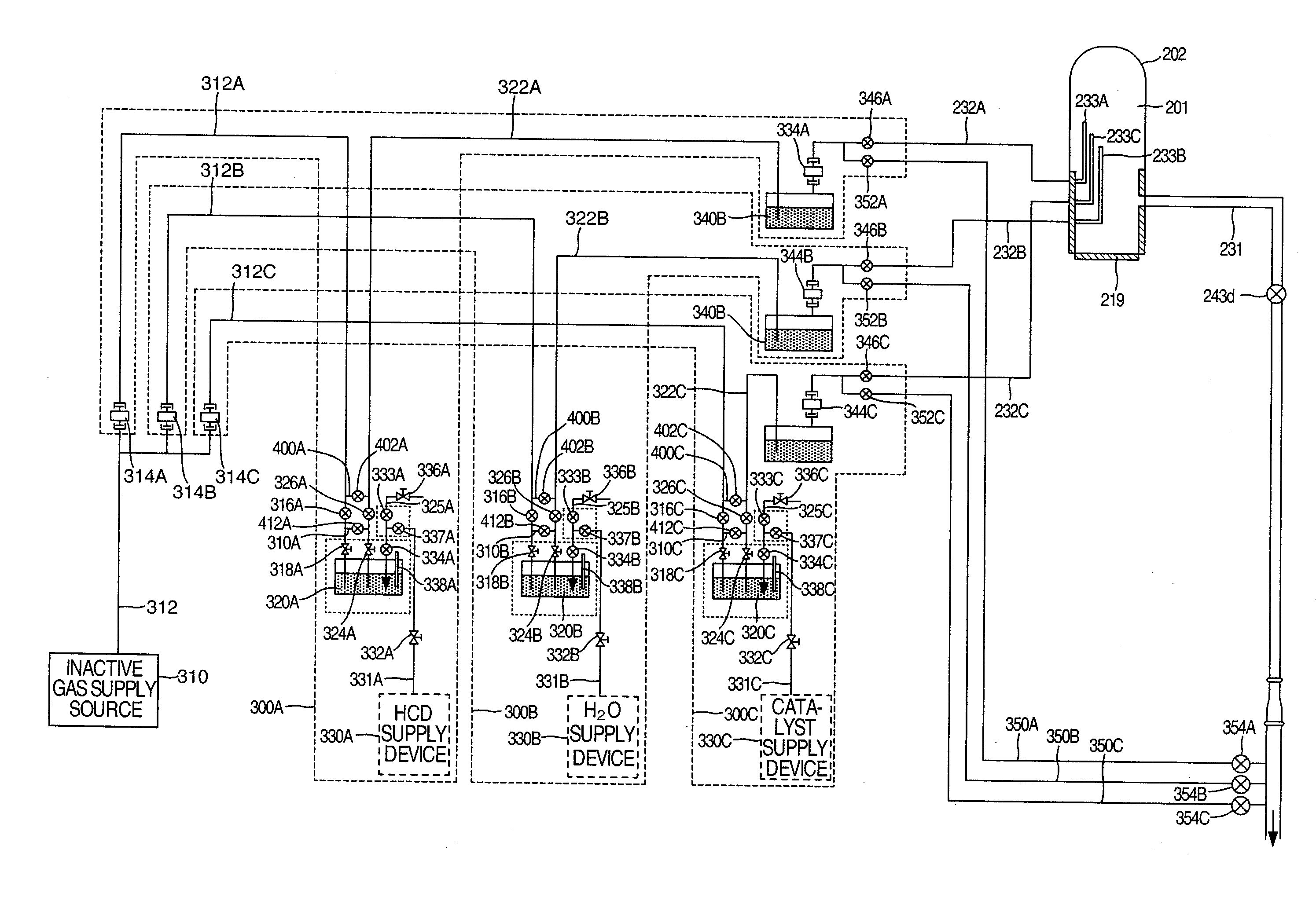
[0104]Although in the embodiment 1 there was described the case where the film formation is performed by ALD method by use of a single kind of liquid raw material for one kind of film seed, another case will be explained with reference to FIG. 7 below, which is for performing the film formation by ALD method by using three kinds of liquid raw materials. Note that members similar to those of FIG. 3 are added similar reference numerals, and detailed explanations are eliminated herein. Also note that each raw material gas supply source and its constituent members are designated by reference numerals with a character (A, B or C) being added thereto at a tail end of reference numeral, which is different from that of another raw material gas supply source and its constituent members, in order to distinguish it from the another raw material gas supply source and its constituent members.

[0105]For example, in the case of forming a SiO2 film by using a catalytic agent, HCD (hexachlorodisilane...


PUM


Abstract

A substrate processing apparatus which stably supplies a vaporized gas of liquid raw material to a processing chamber includes liquid raw material tanks storing a liquid raw material, a carrier gas supply line supplying a carrier gas to one of the tanks, a raw material supply line pressure-feeding to this tank the liquid raw material of the other tank, a carrier gas supply line feeding a carrier gas to the tank, a raw material supply line feeding to the processing chamber a vaporized gas of the liquid raw material of the tank, a mass flow controller which controls the flow rate of the carrier gas, a mass flow controller detecting the flow rate of the vaporized gas of the liquid raw material, and a feedback device feeding back a detection result of the mass flow controller to the former mass flow controller.

Description

INCORPORATION BY REFERENCE[0001]The present application claims priorities from Japanese applications JP2007-151605 filed on Jun. 7, 2007 and JP2008-126721, filed on May 14, 2008, the contents of which are hereby incorporated by reference into this application.BACKGROUND OF THE INVENTION[0002]This invention relates to substrate processing apparatuses and, in particular, to a substrate processing apparatus for processing a substrate by use of a vaporized gas of liquid raw material.[0003]As one example of this type of substrate processing apparatus, there is known an apparatus which employs the so-called bubbling technique for supplying a carrier gas to a liquid raw material tank which stores a liquid raw material to thereby feed a vaporized gas of the liquid raw material to a processing chamber. In this apparatus, the feed amount of the vaporized gas of liquid raw material to the processing chamber is controlled, in some cases, by the feed rate of a carrier gas being supplied to the l...

Claims


Application Information

Patent Timeline
IPC IPC(8): G05D7/00
CPCG05D7/0641
Inventor HONDA, KOICHI
Owner NTT MOBILE COMM NETWORK INC
Learn More