
Process for dithering a time to digital converter and circuits for performing said process

a technology of digital converter and process, applied in the field of synthesizing frequency processes and circuits, can solve the problems of limiting the resolution of oscillators, cycles within the noise spectrum, and the inability to fully digitally implement, and achieve the effect of low cost and easy implementation

Active Publication Date: 2008-12-04
STMICROELECTRONICS SRL
View PDF1 Cites 37 Cited by
  • Summary
  • Abstract
  • Description
  • Claims
  • Application Information

AI Technical Summary

Benefits of technology

[0026]One embodiment provides an easier solution that allows a direct integration of a dithering technique within the TDC converter, so as to keep simple the architecture of the frequency synthesizing circuit.
[0027]One embodiment provides a simple implementation of a dithering process, directly within a Time to Digital converter.
[0029]One embodiment provides a frequency synthesizer which is easy to implement and which comprises a mechanism for inserting a random noise in order to embody a dithering function.
[0030]One embodiment achieves a low cost frequency synthesizing circuit which can be used for telecommunication equipment.

Problems solved by technology

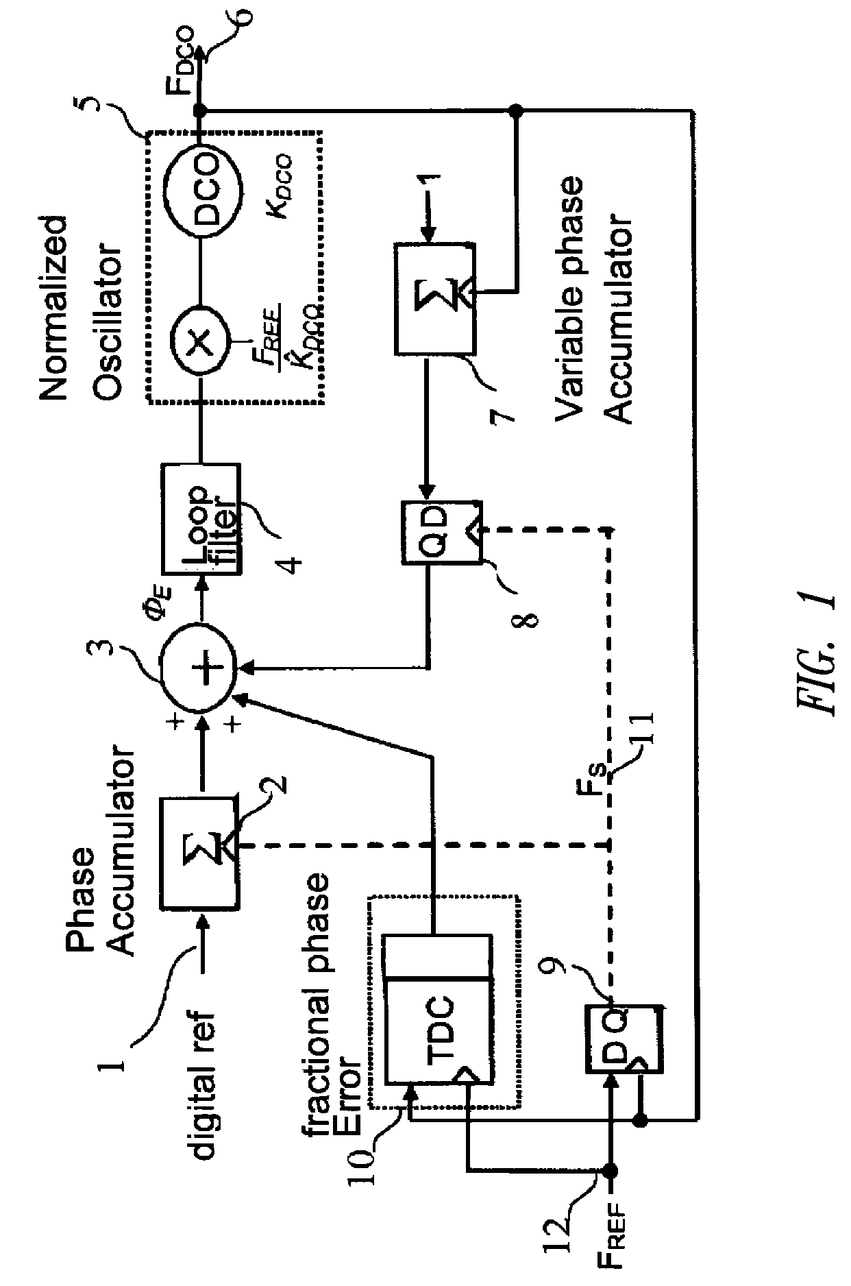
Such a fully digital implementation presents a drawback resulting from the presence of limit cycles within the noise spectrum, as illustrated in FIG. 2.
Limit cycles result from the limitation of the resolution of oscillator 5, which limitation is derived from the quantification step used in the digital frequency synthesis.
When the loop control becomes working, one can thus notice the appearance of jitter, that is to say the successive generation of two neighboring frequencies being one quantification step apart, and such jitter causes the appearance of parasitic lines as shown in FIG. 2, thus resulting in a non negligible quantification noise.
In such a situation, one notices a maximum effect of the limit cycles, thus resulting in a non satisfactory quantification noise.
Generally speaking, known dithering techniques are difficult to embody and results in additional electronic circuits significantly jeopardizing the simplicity of the digital architecture.
On the other hand, the implementations show to be complex and particularly require significant changes at the level of every element composing the synthesizing circuit.

Method used


Image

  • Process for dithering a time to digital converter and circuits for performing said process
  • Process for dithering a time to digital converter and circuits for performing said process
  • Process for dithering a time to digital converter and circuits for performing said process

Examples


Embodiment Construction

[0061]In the following description, numerous specific details are given to provide a thorough understanding of embodiments. The embodiments can be practiced without one or more of the specific details, or with other methods, components, materials, etc. In other instances, well-known structures, materials, or operations are not shown or described in detail to avoid obscuring aspects of the embodiments.

[0062]Reference throughout this specification to “one embodiment” or “an embodiment” means that a particular feature, structure, or characteristic described in connection with the embodiment is included in at least one embodiment. Thus, the appearances of the phrases “in one embodiment” or “in an embodiment” in various places throughout this specification are not necessarily all referring to the same embodiment. Furthermore, the particular features, structures, or characteristics may be combined in any suitable manner in one or more embodiments.

[0063]The headings provided herein are for...


PUM


Abstract

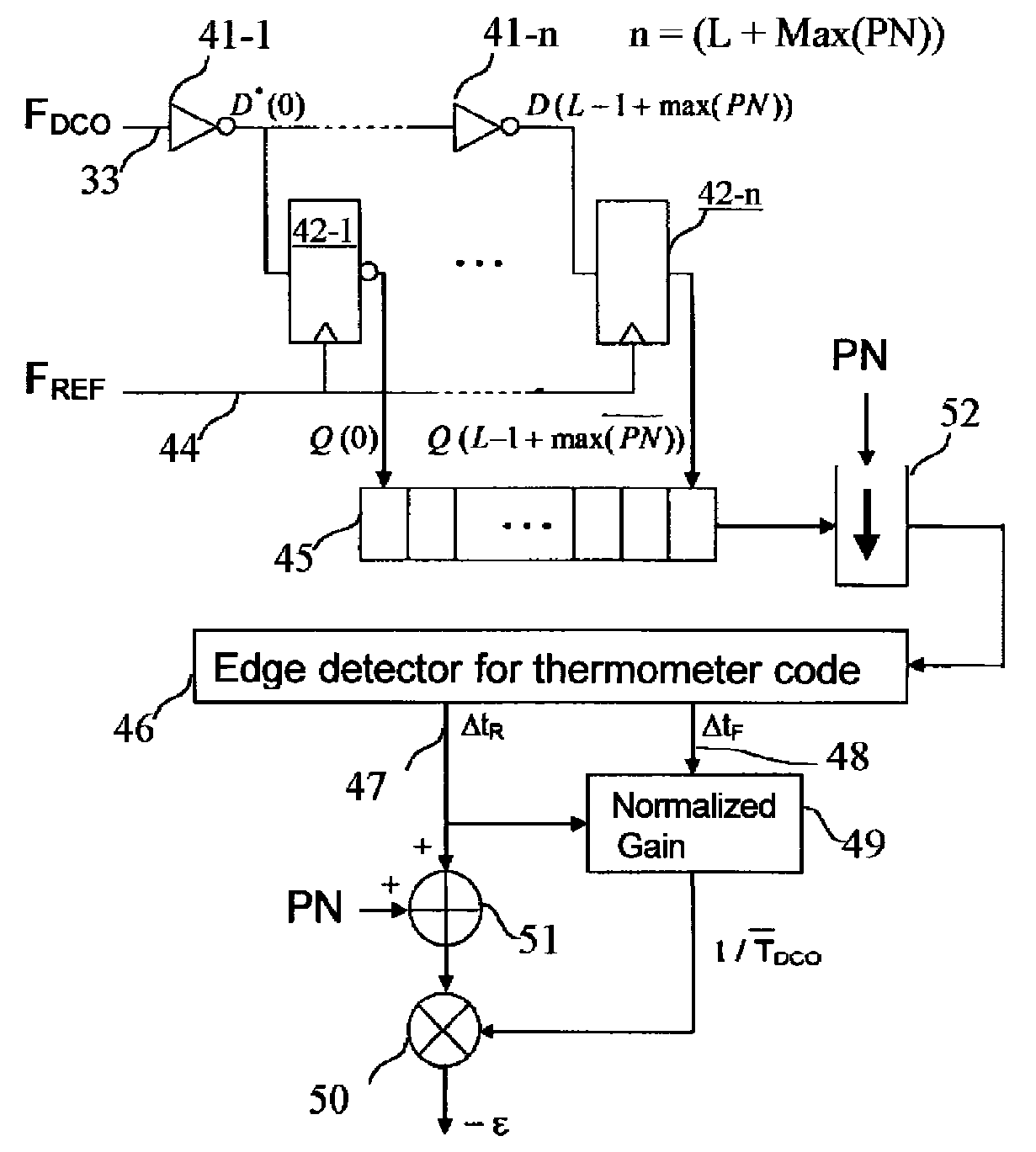
A process inserts a random noise in a Time to Digital Converter (TDC) designed for calculating the phase error between a first high frequency signal FDCO with respect to a second reference signal, switching at a lower frequency. The process involves: processing of the first signal FDCO by using a chain of delays having a set of n elementary delays which number is chosen so as to extend over a full period of the first signal; storing the outputs of the chain of delays in a set of latches and generation of a thermometer code presenting a stream of “1” separated from a stream of “0” by a border corresponding to the transition of the first signal with respect to the second reference signal; reducing the thermometer code by a random number PN of bits; processing of the result in an edge detecting and thermometer code decoding so as to generate two variables Δtr and Δtf which are representative of the difference between the rise and fall time of the first signal with respect to the second reference signal; computing the normalized gain so as to generate an average value of 1 / TDCO; adding to the value Δtr a binary value corresponding to the number of bits PN; multiplying the preceding result by the average value of 1 / TDCO and computing the phase error between the signals. The delay chain may be arranged with inverters. The process is particularly but not exclusively useful for carrying out a TDC convertor for the purpose of synthesizing of frequencies.

Description

TECHNICAL FIELD[0001]The present disclosure generally relates to processes and circuits for synthesizing frequencies, and more particularly but not exclusively to a process for dithering a Time to Digital Converter (T.D.C.).BACKGROUND INFORMATION[0002]Frequency synthesizing circuits are widely used in the architecture of electronic circuits, particularly in the field of telecommunications.[0003]Usually, the problem involves producing a sinusoidal signal which has a frequency having a value which is equal to n times the value of a reference frequency, said frequency being assumed to be steady, such as generated by a quartz oscillator.[0004]In such a situation, the frequency synthesis is achieved by using a Phase Locked Loop (P.L.L.) circuit and the recent general tendency is now to use fully digital architectures for embodying such circuits.[0005]FIG. 1 illustrates a digital architecture of a known frequency synthesizer generating, at an output 6, a high frequency having a value FDCO...

Claims


Application Information

Patent Timeline
IPC IPC(8): H03B21/00
CPCG04F10/005H03L7/091
Inventor BAUDIN, PIERREJOUBERT, CYRIL
Owner STMICROELECTRONICS SRL
Learn More