
Bonded Fuel Cell Assembly and Methods and Systems for Producing the Same

a fuel cell and assembly technology, applied in the direction of electrochemical generators, paper/cardboard containers, manufacturing tools, etc., can solve the problems of affecting the performance of the fuel cell, and reducing the service life of the fuel cell

Inactive Publication Date: 2008-11-27
BURDZY MATTHEW PETER +2
View PDF37 Cites 10 Cited by
  • Summary
  • Abstract
  • Description
  • Claims
  • Application Information

AI Technical Summary

Benefits of technology

[0012]The present invention provides a method, a composition and a system to bond and seal fuel cell components. The sealant composition used to bond and seal fuel cell parts may include two or more components that separately are stable, however, when combined or exposed to an energy sour...

Problems solved by technology

Such silicone compositions, however, degrade before the desired operating lifetime of the fuel cell is achieved.
Also, such silicone rubbers release materials that contaminate the fuel cell, thereby adversely affecting the performance of the fuel cell.
The application of these compositions, however, is time consuming as each individual element of the fuel cell or each arrangement of fuel cell components have to be individually bonded with these compositions.
Application temperatures suitable for bonding the thermoplastic film may limit the design of a fuel cell and also are difficult to apply as aligned stacks of fuel cell components have to be heated and cooled under controlled conditions.
The placement of the adhesives and the gaskets are not only time consuming, but problematic because misalignment may cause leakage and loss of performance of the fuel cell.
The cross-linked density and the resultant properties of these compositions are limited by using linear polyisobutylene oligomers having an allyl or alkenyl functionality of two.
Functionality of these compositions is modified by varying the hydrosilyl functionality, which limits the properties of the resultant compositions.
The use of solid gaskets, i.e., foam rubber and / or solid fluoroplastic tape or film, makes placement of these materials and subsequent alignment of the fuel cell components and gaskets time consuming and problematic.
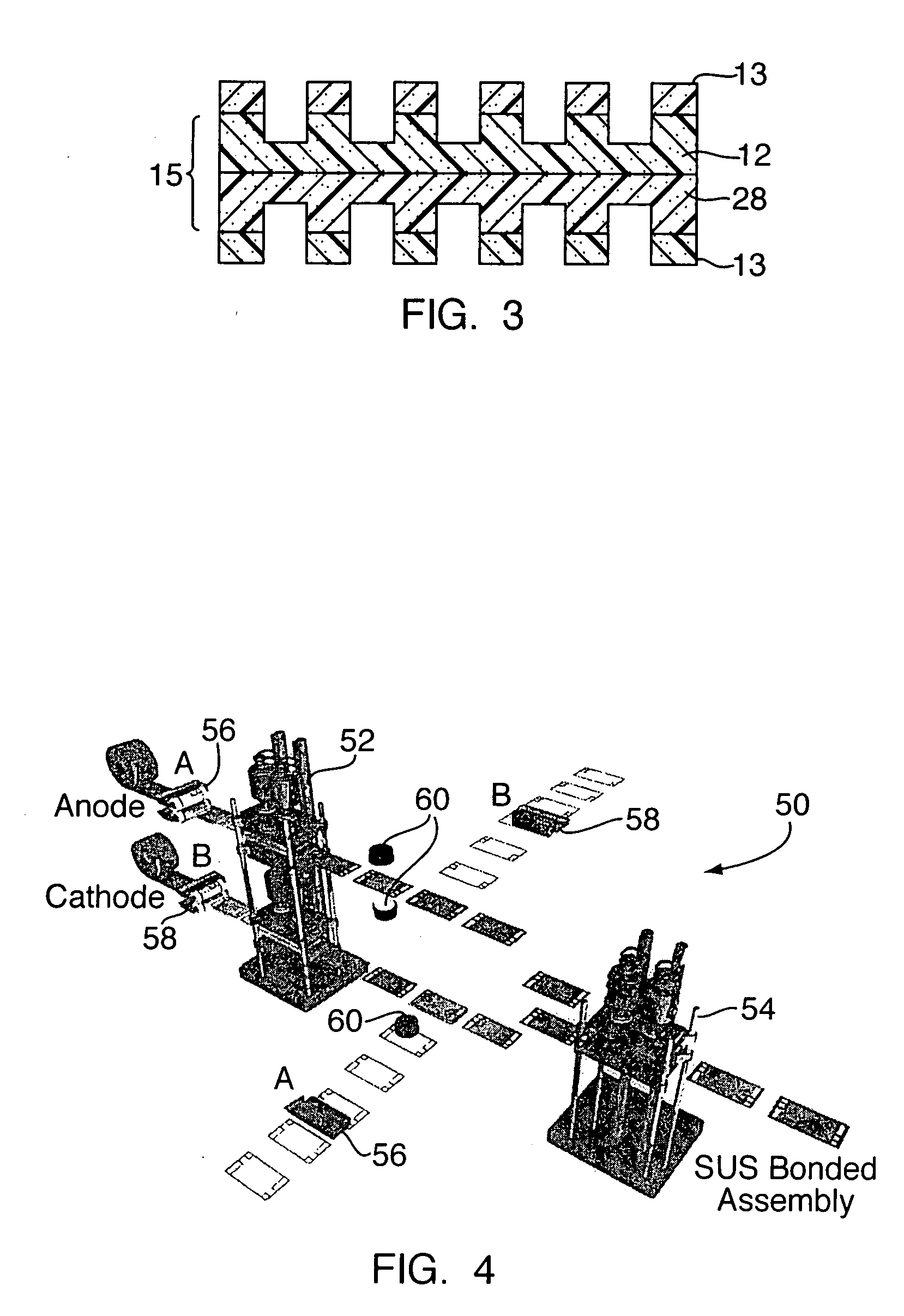
While this publication describes an automated process for forming fuel cell electrodes, the publication fails to address the sealing concerns of the formed fuel cells.

Method used


Image

  • Bonded Fuel Cell Assembly and Methods and Systems for Producing the Same
  • Bonded Fuel Cell Assembly and Methods and Systems for Producing the Same
  • Bonded Fuel Cell Assembly and Methods and Systems for Producing the Same

Examples


Embodiment Construction

[0020]The present invention is directed to a method for bonding and compositions for bonding components of an electrochemical cell. As used herein, an electrochemical cell is a device which produces electricity from chemical sources, including but not limited to chemical reactions and chemical combustion. Useful electrochemical cells include fuel cells, dry cells, wet cells and the like. A fuel cell, which is described in greater detail below, uses chemicals reactants to produce electricity. A wet cell has a liquid electrolyte. A dry cell has an electrolyte absorbed in a porous medium or otherwise restrained from being flowable.

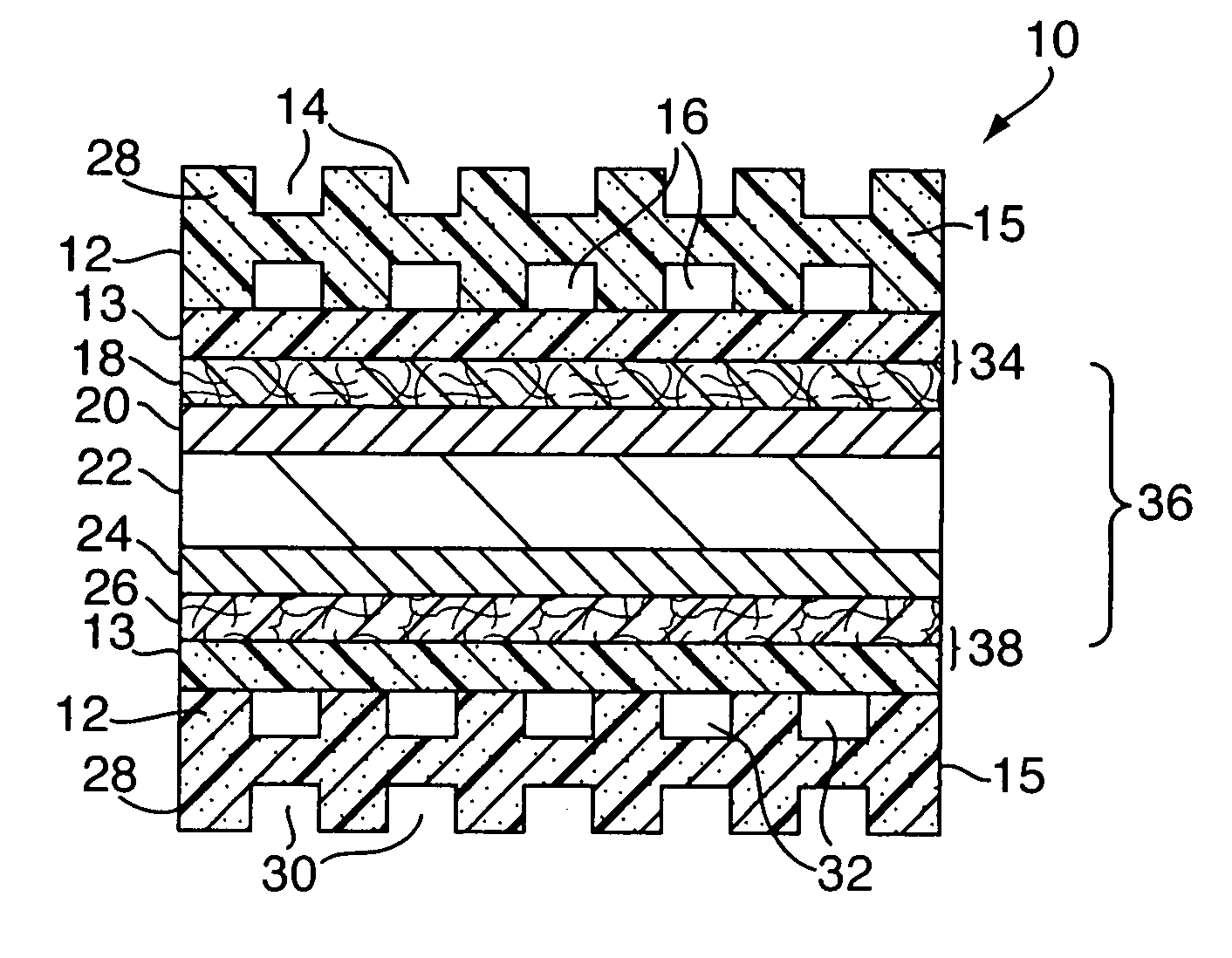
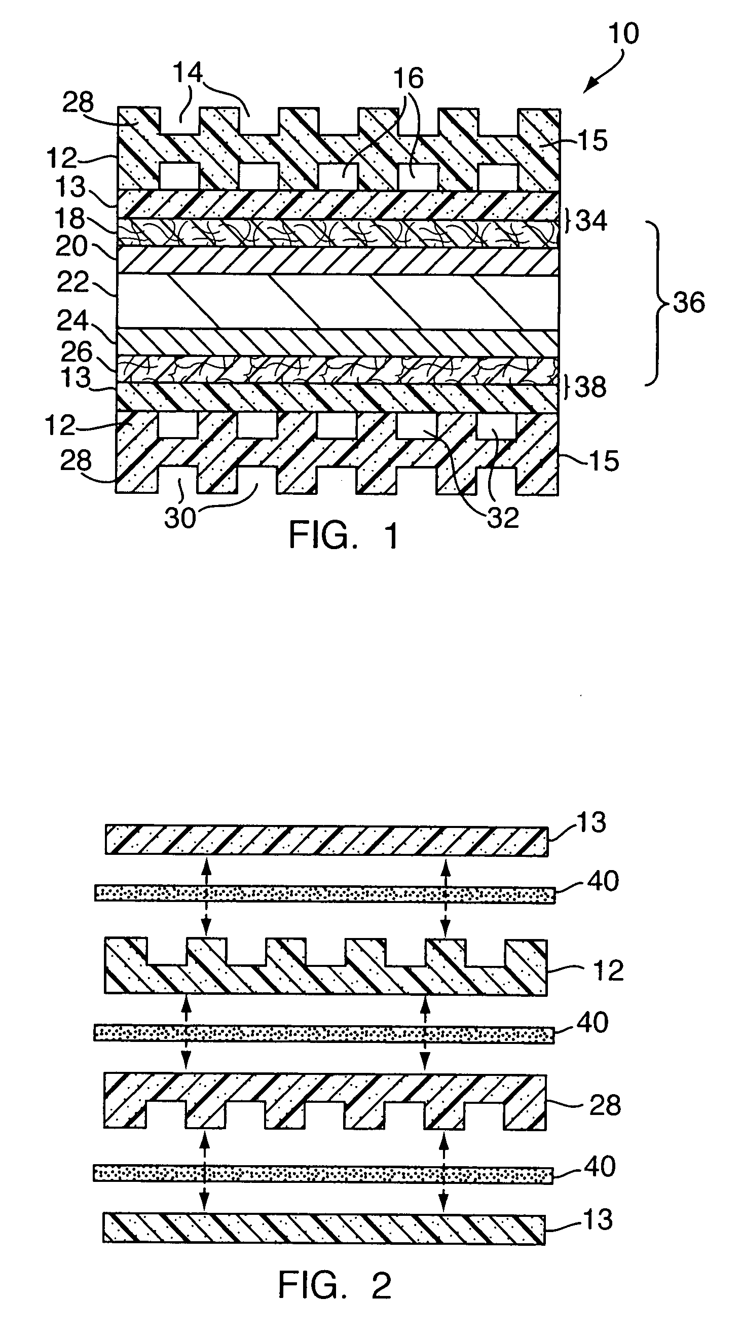
[0021]FIG. 1 shows a cross-sectional view of the basic elements of an electrochemical fuel cell, such as fuel cell 10. Electrochemical fuel cells convert fuel and oxidant to electricity and reaction product. Fuel cell 10 consists of an anode flow field plate 12 with open face coolant channels 14 on one side and anode flow channels 16 on the second side, a res...


PUM


Abstract

A method for forming a fuel cell component includes the steps of providing a two-part sealant having a first part comprising an initiator and a second part comprising a polymerizable material; applying the first part of the sealant to a substrate of a first fuel cell component; applying the second part of the sealant to a substrate of a second fuel cell component; juxtaposingly aligning the substrates of the first and second fuel cell components; and curing the sealant to bond the first and second fuel components to one and the other. The initiator may be an actinic radiation initiator, whereby the sealant is cured by actinic radiation. The polymerizable material may be a polymerizable monomer, oligomer, telechelic polymer, functional polymer and combinations thereof. Desirably, the functional group is epoxy, allyl, vinyl, acrylate, methacrylate, imide, amide, urethane and combinations thereof. Useful fuel cell components to be bonded include a cathode flow field plate, an anode flow field plate, a resin frame, a gas diffusion layer, an anode catalyst layer, a cathode catalyst layer, a membrane electrolyte, a membrane-electrode-assembly frame, and combinations thereof.

Description

FIELD OF THE INVENTION[0001]The present invention relates to a method for bonding and sealing components of an electrochemical cell, such as a fuel cell, and an electrochemical cell formed therefrom. More particularly, the present invention relates to a method and design for bonding fuel cell components in a manner suitable for continuous production of the fuel cell components.BRIEF DESCRIPTION OF RELATED TECHNOLOGY[0002]Although there are various known types of electrochemical cells, one common type is a fuel cell, such as a proton exchange membrane (“PEM”) fuel cell. The PEM fuel cell contains a membrane electrode assembly (“MEA”) provided between two flow field plates or bipolar plates. Gaskets are used between the bipolar plates and the MEA to provide seals thereat. Additionally, since an individual PEM fuel cell typically provides relatively low voltage or power, multiple PEM fuel cells are stacked to increase the overall electrical output of the resulting fuel cell assembly. S...

Claims


Application Information

Patent Timeline
IPC IPC(8): B32B37/00C09J163/00
CPCH01M8/0273H01M8/0284Y10T156/10Y02E60/523Y02E60/50H01M8/0297Y02P70/50H01M8/02H01M8/04H01M8/2484H01M8/2483H01M8/0258H01M8/0267
Inventor BURDZY, MATTHEW PETEREINSLA, BRIAN RUSSELLWELCH, KEVIN JAMES
Owner BURDZY MATTHEW PETER
Learn More