
Voltage generator that prevents latch-up

Inactive Publication Date: 2008-11-20
SAMSUNG ELECTRONICS CO LTD
View PDF2 Cites 13 Cited by
  • Summary
  • Abstract
  • Description
  • Claims
  • Application Information

AI Technical Summary

Benefits of technology

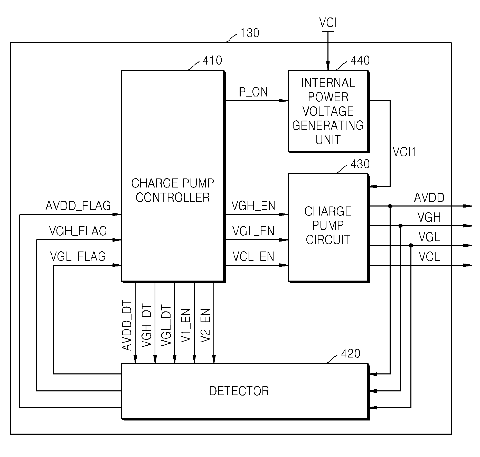
[0025]Exemplary embodiments of the present invention provide a voltage generator and voltage generating method for preventing latch-up that may occur in a boosting mode or in a normal operation mode.
[0046]Therefore, the voltage generator and voltage generating method can prevent latch-up that may occur in a boosting mode or in a normal operation mode.

Problems solved by technology

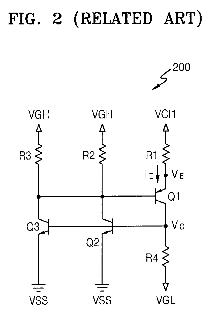
Latch-up indicates that a thyristor operation occurs at a PNPN junction included in a CMOS chip, so that excessive current flows through the chip, thereby causing destruction of the chip.
Although latch-up occurs in an instant, once a chip is in a latch-up state, the latch-up state is continuously maintained until the power is blocked by a thyristor structure, thereby ultimately causing destruction of the chip.
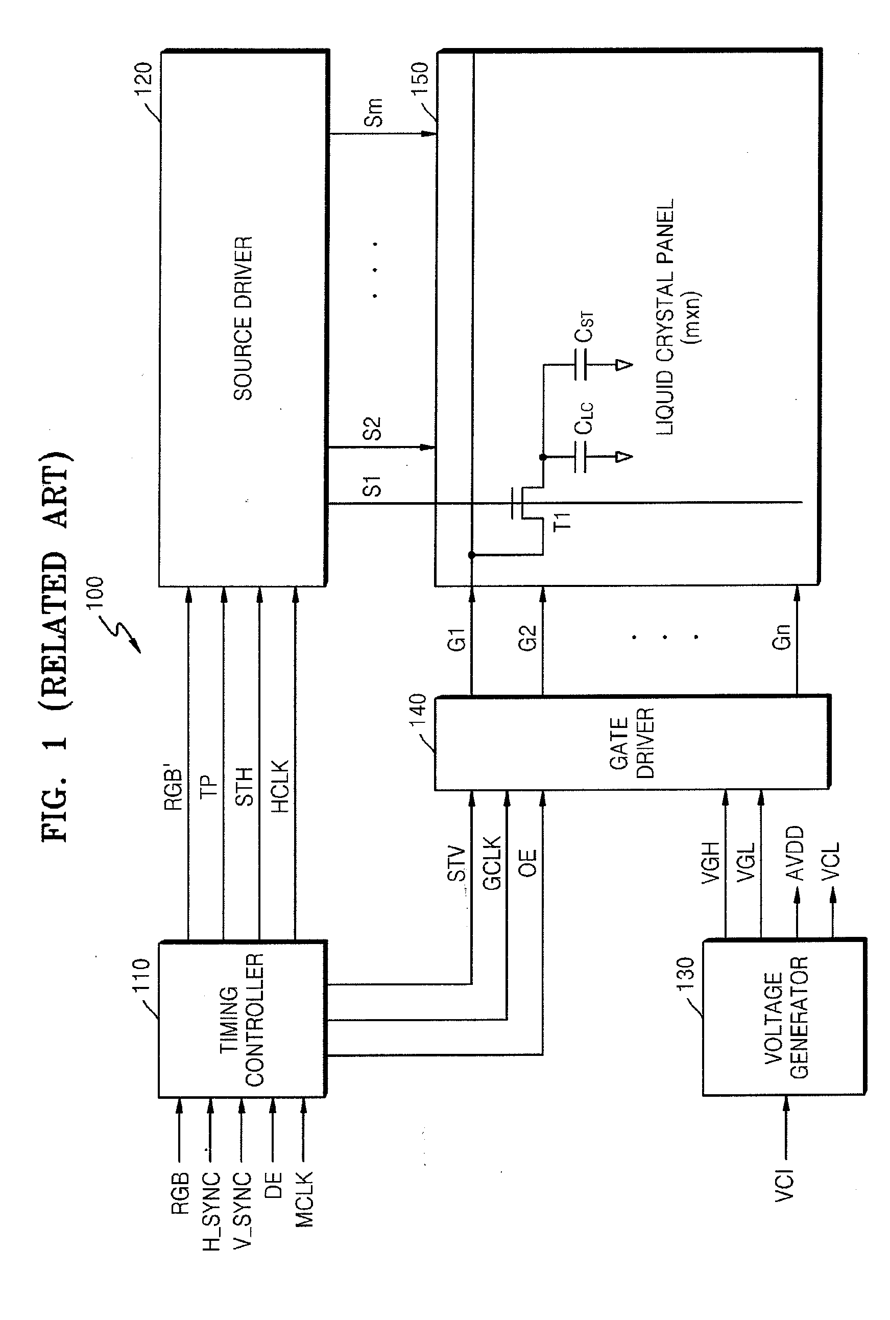
As described above, in a boosting mode of the voltage generator 130, when latch-up occurs due to momentary forward biasing, the circuit may be seriously damaged.

Method used


Image

  • Voltage generator that prevents latch-up
  • Voltage generator that prevents latch-up
  • Voltage generator that prevents latch-up

Examples


Embodiment Construction

[0057]Hereinafter, the present invention will be described more fully with reference to the accompanying drawings, in which exemplary embodiments of the invention are shown. In the drawings, like reference numerals denote like elements.

[0058]FIG. 3 is a timing diagram of enable signals and voltages related to a voltage generator according to an exemplary embodiment of the present invention.

[0059]Referring to FIG. 3, the voltage generator 130 according to an exemplary embodiment of the present invention can prevent latch-up in both a boosting mode MD1 section and a normal operation mode MD2 section.

[0060]First, an operation of the voltage generator 130 in the boosting mode MD1 will be described.

[0061]When an external power voltage VCI starts to be supplied, the voltage generator 130 generates an internal power voltage VCI1 from a power-on signal P-ON as a starting point. In FIG. 3, the level of the internal power voltage VCI1 is higher than that of the external power voltage VCI. The...


PUM


Abstract

A voltage generator that prevents latch-up includes: a charge pump circuit that is controlled by first through third enable signals, boosts an internal power voltage generated from an external power voltage, and generates first through fourth voltages; a detector that detects the first through third voltages and generates first through third flag signals that go logic high when the first through third voltages reach predetermined respective voltage levels and maintain logic low when the voltages do not reach the predetermined respective voltage levels; and a charge pump controller that receives the first through third flag signals, and generates the first through third enable signals to have the first through fourth voltages sequentially generated. The voltage generator can prevent latch-up that may occur in a boosting mode or in a normal operation mode.

Description

CROSS-REFERENCE TO RELATED PATENT APPLICATION[0001]This application claims the benefit of Korean Patent Application No. 10-2007-0046663, filed on May 14, 2007, in the Korean Intellectual Property Office, the disclosure of which is incorporated herein in its entirety by reference.BACKGROUND OF THE INVENTION[0002]1. Technical Field Invention[0003]The present disclosure relates to a voltage generator of a liquid crystal display (LCD) and, more particularly, to a voltage generator that prevents latch-up.[0004]2. Discussion of Related Art[0005]In a voltage generating circuit, for example, in a complementary metal oxide semiconductor (CMOS) device used generally in a charge pump circuit, a specific state called latch-up exists.[0006]Latch-up indicates that a thyristor operation occurs at a PNPN junction included in a CMOS chip, so that excessive current flows through the chip, thereby causing destruction of the chip. Latch-up occurs when input and output voltages exceed a rated level and ...

Claims


Application Information

Patent Timeline
IPC IPC(8): G05F3/02G09G5/00
CPCG09G3/3696H02M3/073H02M2001/009H02M1/009G02F1/133G09G3/36H02M3/07
Inventor KIM, HYO-JINKANG, JAE-SUNGKIM, JONG-WONKIM, SI-WOO
Owner SAMSUNG ELECTRONICS CO LTD
Learn More