Nitride Sintered Body and Method for Manufacturing Thereof

Inactive Publication Date: 2008-11-20
TOKUYAMA CORP
View PDF11 Cites 0 Cited by
  • Summary
  • Abstract
  • Description
  • Claims
  • Application Information

AI Technical Summary

Benefits of technology

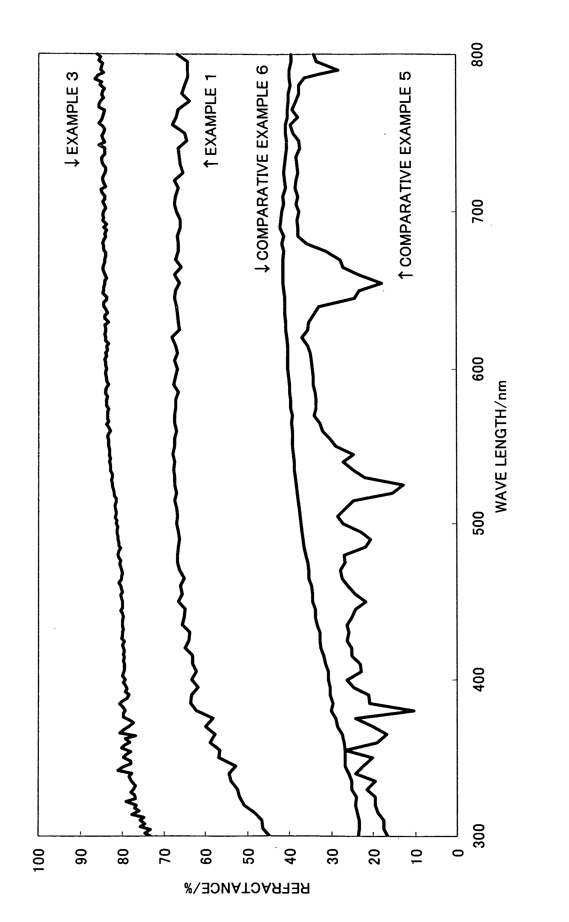
[0025]High luminance can be realized in a compound light emitting element of the invention using the sintered body since a nitride sintered body of the invention has a high light reflectance and therefore, light propagating toward a submount element from a light emitting element is effectively reflected toward a main light take-out surface side. The nitride sintered body of the invention can be preferably used as a submount for a white LED since a reflectance, especially, of light with a wavelength of 700 nm is high. As the thermal conductivity of a nitride sintered body of the invention is 50 (W / m·K) or more, the compound light emitting body using the nitride sintered body has a high dissipation of heat generated by LED, resulting in high durability and reliability. A nitride sintered body of the invention has the following two aspects: 1) the nitride sintered body consists of an aluminum nitride sintered body that sintering thereof has sufficiently advanced with a high density, a very high thermal conductivity and very high mechanical strength thereof and 2) the nitride sintered body has a very high light reflectance though a densification level of sintering is not high. Therefore, a compound light emitting element of the invention using an aluminum nitride sintered body in 1) is characterized by that radiatablity of heat generated in an LED, durability and reliability are especially high. In addition, a compound light emitting element of the invention using a nitride sintered body in 2) is characterized by that an effect of progress toward high luminance is especially excellent.

Problems solved by technology

Conventionally, a silicon substrate has been used as a submount, while there has been a problem that a compound light emitting element is reduced in luminance thereof since the silicon substrate absorbs light in the wavelength range of from 450 nm (blue) to 560 nm (green) emitted from an LED.
In recent years, however, a problem has occurred that a generated heat quantity from an LED increases in company with progress toward high luminance, thereby raising an element temperature.
Though such a problem is thought to be able to be solved by constituting a submount with an insulating material high both in thermal conductivity and light reflectance, no insulating material meeting such a requirement has been found.
On the other hand, nitride sintered bodies including aluminum nitride sintered body or silicon nitride sintered body have been known as an insulating material high in thermal conductivity, whereas a nitride sintered body that has been conventionally known has a problem in the aspect of a light reflectance.

Method used


Image

  • Nitride Sintered Body and Method for Manufacturing Thereof
  • Nitride Sintered Body and Method for Manufacturing Thereof
  • Nitride Sintered Body and Method for Manufacturing Thereof

Examples


examples

[0091]The invention will be specifically explained referred to examples, it should be understood that the invention is not limited to the examples.

first embodiment

Example 1

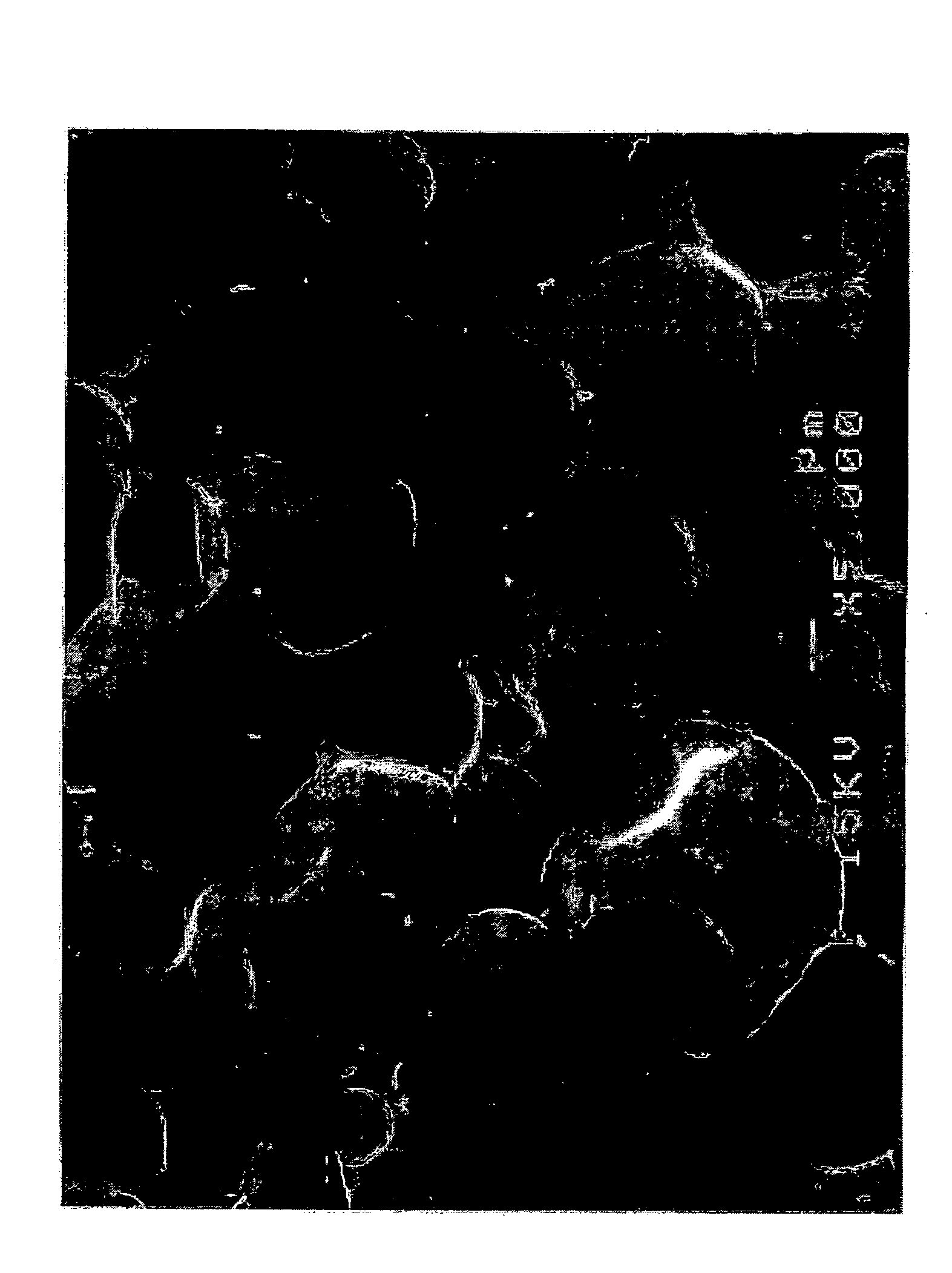
[0092]Mixed together were 100 parts by mass of an aluminum nitride powder having an average particle diameter of 1.5 μm, and an oxygen concentration of 0.8 wt % and 5 parts by mass of 3CaO.Al2O3. Then, ethanol was added into the mixture, which was mixed using a ball mill and dried to obtain mixed powder, and the mixed powder was CIP formed to obtain a preform having a diameter of 40 mm and a thickness of 5 mm, followed by degreasing in an oxidizing atmosphere of air. The obtained preform (degreased preform) and a carbon plate with a surface area of 320 mm2 (a standard carbon plate having a plan view of a square with a size of 40 mm, a thickness thereof was 3 mm and a weight of 18 g was cut into pieces each having a size (10 mm×10 mm×3 mm thick as samples) with a side ¼ times that of the standard carbon plate) were put into a carbon made vessel with a cover, the inner wall of which is made of boron nitride, and which has an inside volume of 84 cm3, so that the obtained prefo...

second embodiment

Example 3 and Example 4

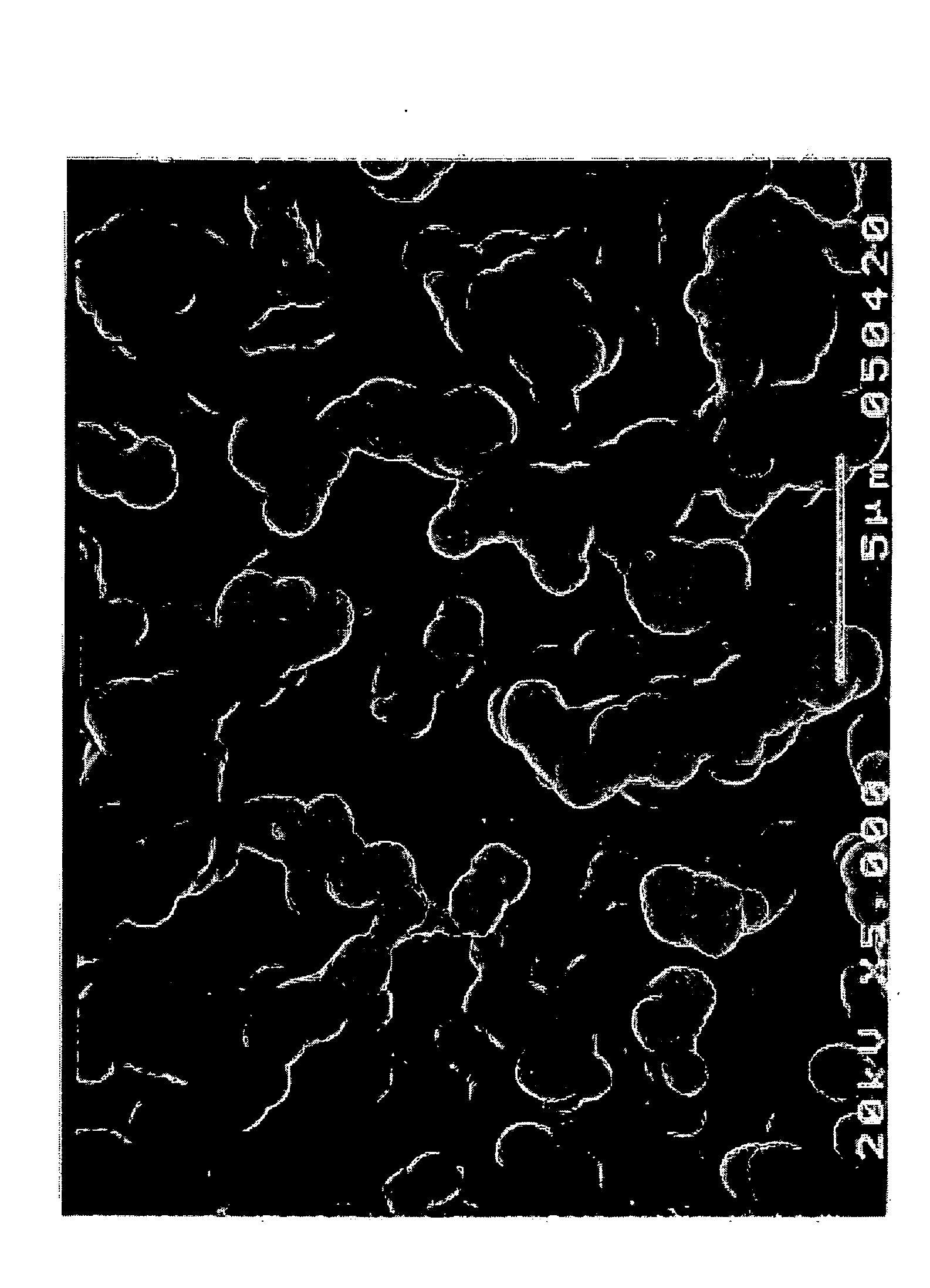
[0095]Kneaded together were 100 parts by mass of an aluminum nitride powder (having an oxygen concentration of 0.8 mass %) having an average particle diameter of 1.5 μm, 5 parts by mass of yttrium oxide (Y2O3) powder having an average diameter of 0.5 μm, 9 parts by mass of ethyl cellulose and 40 parts by mass of terpinol to thereby prepare an aluminum nitride paste having an adjusted viscosity of 3500 cP at 25° C. An aluminum nitride powder having an average diameter of 1.5 μm and yttrium oxide as a sintering assistant were added to the aluminum nitride paste and the resultant aluminum nitride paste was sintered to obtain an aluminum nitride sintered body substrate, the aluminum nitride paste was screen printed on a surface of a base substrate made of the aluminum nitride sintered body substrate to a thickness of 300 μm and the screen-printed base substrate was dried at 80° C. for 5 min. Thus obtained substrate was burned in a similar way to that in Example 1 ...


PUM

PropertyMeasurementUnit
Temperatureaaaaaaaaaa
Lengthaaaaaaaaaa

Abstract

An insulating material high both in thermal conductivity and light reflectance, and a submount high in heat radiatability for mounting an LED element thereon, capable of raising a light utilization factor and quickly radiating heat generated from the element. For example, used as a substrate material of a submount is a nitride sintered body having a reflectance of light in the wavelength region of from 350 nm to 800 nm of 50% or more and a reflectance of light with a wavelength of 700 nm of 60% or more, obtained by sintering a preform consisting of a composition containing 100 parts by mass of aluminum nitride powder and 0.5 to 10 parts by mass of a compound containing an alkaline earth metal such as 3CaO×Al2O3 in an inert atmosphere containing a specific quantity of carbon vapor, or by burning a coat of a nitride paste applied on a base substrate having a heat resistance at a predetermined temperature.

Description

BACKGROUND OF THE INVENTION[0001]1. Field of the Invention[0002]The invention relates to a nitride sintered body having a high thermal conductivity and a high reflectance in the visible light region and a method for manufacturing thereof.[0003]2. Description of the Background Art[0004]Monochromatic light emitting diodes (a light emitting diode is hereinafter referred to as LED) emitting light in colors such as red, green and blue, and a white LED have been introduced commercially, which has increased applications of light emitting elements using LED to a large extent.[0005]For example, an LED emitting blue light using a GaN based compound semiconductor is fabricated and put into practice in a way such that an insulating sapphire is generally adopted as a substrate, p side and n side electrodes are formed on the front surface side of a compound semiconductor stacked on the substrate, which is used as a so-called flip chip type light emitting element surface-mounted on the electrode f...

Claims


Application Information

Patent Timeline
IPC IPC(8): H01J1/62B32B3/26B05D3/00C04B35/64C04B35/581C04B41/87H01L33/48
CPCC04B35/581Y10T428/268C04B35/6264C04B35/6303C04B35/64C04B2235/3205C04B2235/3222C04B2235/3224C04B2235/3225C04B2235/5436C04B2235/5445C04B2235/652C04B2235/656C04B2235/658C04B2235/77C04B2235/85C04B2235/9607C04B2235/9646C04B35/62625Y10T428/249921C04B35/58
Inventor YAMAMOTO, YASUYUKIKANECHIKA, YUKIHIROMAEDA, MASAKATSU
Owner TOKUYAMA CORP
Why Eureka
Try Eureka