
Stable Composite Material Comprising Supported Porous Gels

a technology of porous gels and composite materials, applied in the direction of metal/metal-oxide/metal-hydroxide catalysts, chemical/physical processes, water/sewage treatment by ion exchange, etc., can solve the problems of failure of all attempts, and achieve the effect of high flux

Active Publication Date: 2008-10-30
MERCK MILLIPORE LTD
View PDF36 Cites 100 Cited by
  • Summary
  • Abstract
  • Description
  • Claims
  • Application Information

AI Technical Summary

Benefits of technology

[0022]The porous support member, or host, may be hydrophilic or hydrophobic and can be, for example, in the form of a membrane, a chromatography bed, or a filtration bed. The support member provides the mechanical strength to support the macroporous gel. The macroporous gel provides a low resistance to hydraulic flow, enabling high flow rates to be achieved with low reductions in pressure across the composite material. The macroporous gel also provides the separating function of the composite material in chromatographic and filtration applications.
[0023]A gel is a crosslinked polymer network swollen in a liquid medium. The swelling liquid prevents the polymer network from collapsing and the network, in turn, retains the liquid.
[0030]In the absence of a support member, the macroporous gels used in the present invention may be non-self supporting, and they may change or even lose their porosity when dried. By inserting the macroporous gel within a porous support member, mechanical-strength is conferred upon the macroporous gel. The utilization of macroporous gels creates a composite material that permits larger molecules, such as biological molecules, to enter the macropores and the solution containing such molecules to traverse the gel at a high flux.

Problems solved by technology

While attempts were made to entrap polyelectrolytes in neutral cages, these attempts all met with failure unless the polyelectrolyte was grafted into the cage network or unless the polyelectrolyte was crosslinked.

Method used


Image

  • Stable Composite Material Comprising Supported Porous Gels
  • Stable Composite Material Comprising Supported Porous Gels
  • Stable Composite Material Comprising Supported Porous Gels

Examples


example 1

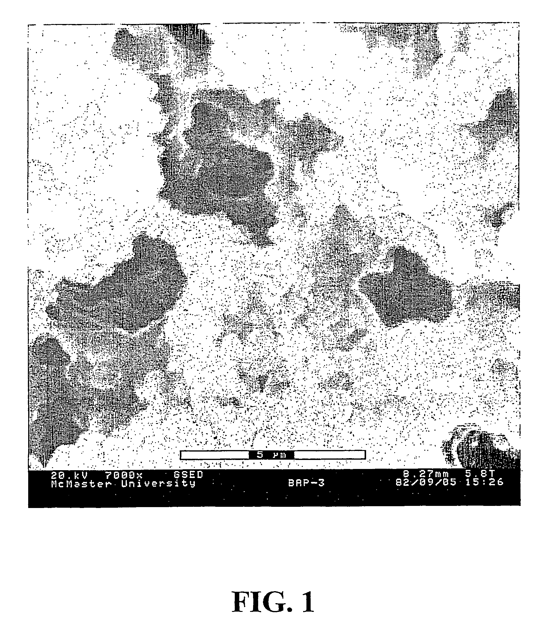
[0182]This example illustrates the formation of an unsupported porous gel, which can be used as the macroporous gel to prepare the composite material of the invention.

[0183]A solution containing 3.33 g of (3-acrylamidopropane)trimethylammonium chloride (APTAC) monomer as a 75% aqueous solution, 0.373 g of N,N′-methylenebisacrylamide (BIS) crosslinker, and 0.0325 g of Irgacure®2959 photoinitiator dissolved in 25 ml of a dioxane:dimethylformamide:water mixture, with the solvent volume ratio of 71:12:17, respectively, was prepared. In this solvent mixture, dioxane is a poor solvent while DMF and water are good solvents. A total monomer concentration (APTAC and BIS) of 0.58 mol / L was thus obtained. The crosslinking degree was 20 mol %, based on APTAC. 5 ml of this solution was placed in a glass vial and subjected to UV irradiation at 350 nm for 2 hrs. A white gel was formed which was washed thoroughly with de-ionized water to exchange the reaction solvent and remove the unreacted monome...

example 2

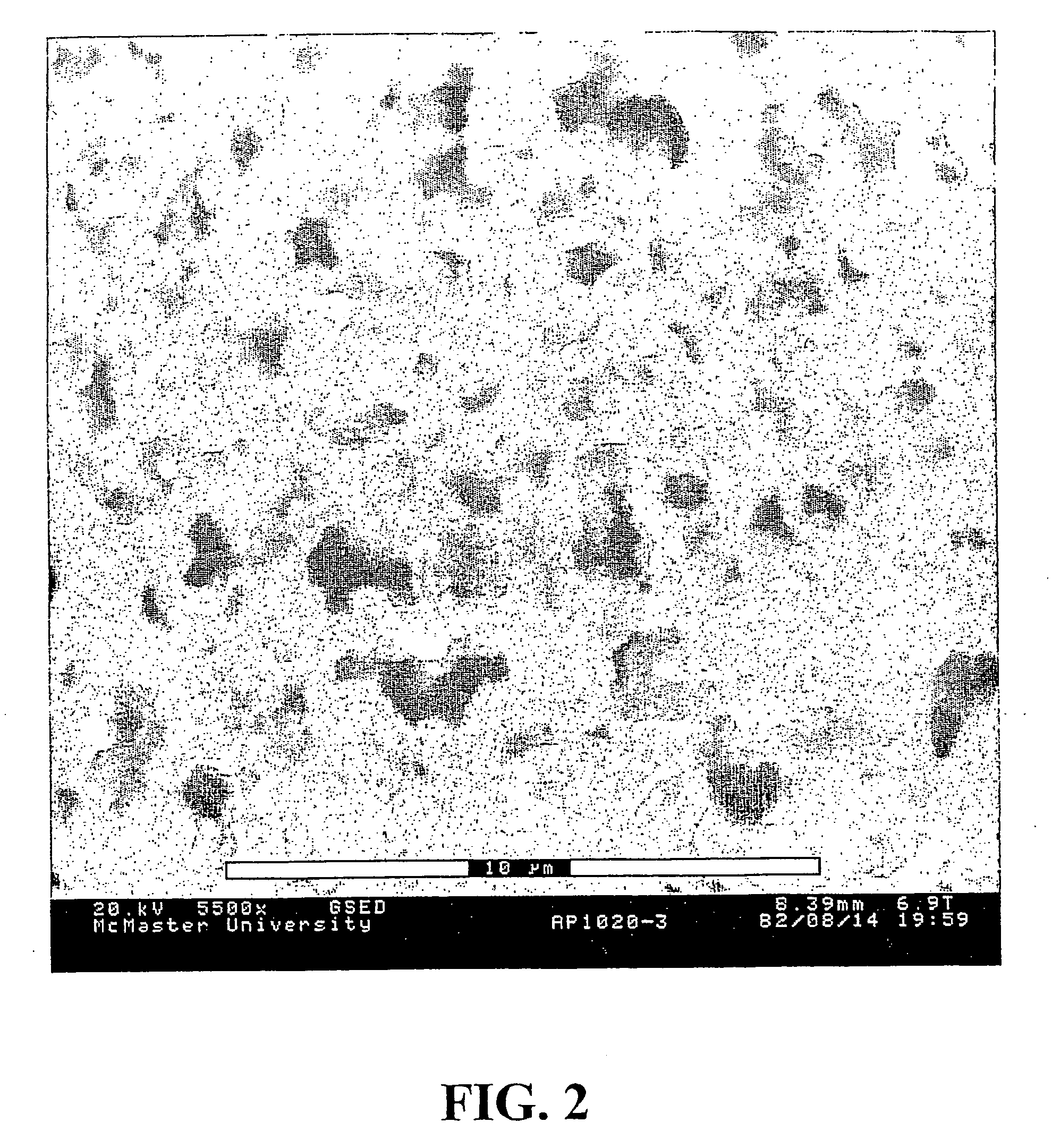
[0185]This example illustrates a method of preparing a positively charged composite material of the present invention using the monomer solution of composition described in example 1 applied to a sample of the poly(propylene) porous support PP1545-4. The composite material was prepared according to the general procedure described above using UV irradiation at 350 nm for 2 hours. After polymerization, the composite material was washed with de-ionized water for 48 hrs.

[0186]Mass gain of the resulting composite material after drying was 107 wt %, water flux was 1643±5 kg / m2 h at 50 kPa and Darcy permeability was 9.53×10⁻¹⁶ m2.

[0187]The morphology of the gel-incorporated composite material was examined using ESEM in the same manner as described in Example 1. The ESEM micrograph shown in FIG. 2 shows that the macroporous gel has been incorporated into the host membrane. The micrograph shows a similar structure to that of the unsupported macroporous gel shown in FIG. 1 and little evidence...

example 3

[0188]This example illustrates a method of preparing a negatively charged composite material of the present invention, with a weak acid functionality.

[0189]5.50 g of vacuum-distilled methacrylic acid (MAA) monomer, 0.4925 g of N,N′-methylenebisacrylamide crosslinker and 0.1503 g of Irgacure® 2959 photoinitiator were dissolved in 25 ml of a dioxane:DMF solvent mixture with a volume ratio of 9:1, respectively, to prepare the starting monomer solution. The composite material was prepared using the poly(propylene) PP1545-4 support and the general procedure for the photoinitiated polymerization described above. The irradiation time used was 2 hours and the resulting membrane was washed with DMF for 24 hrs followed by a 48 hr wash with deionized water. The mass gain of the resulting dried membrane was 231 wt %, water flux was 4276±40 kg / m2 h at 50 kPa and Darcy permeability was 2.64×10⁻¹⁵ m2.

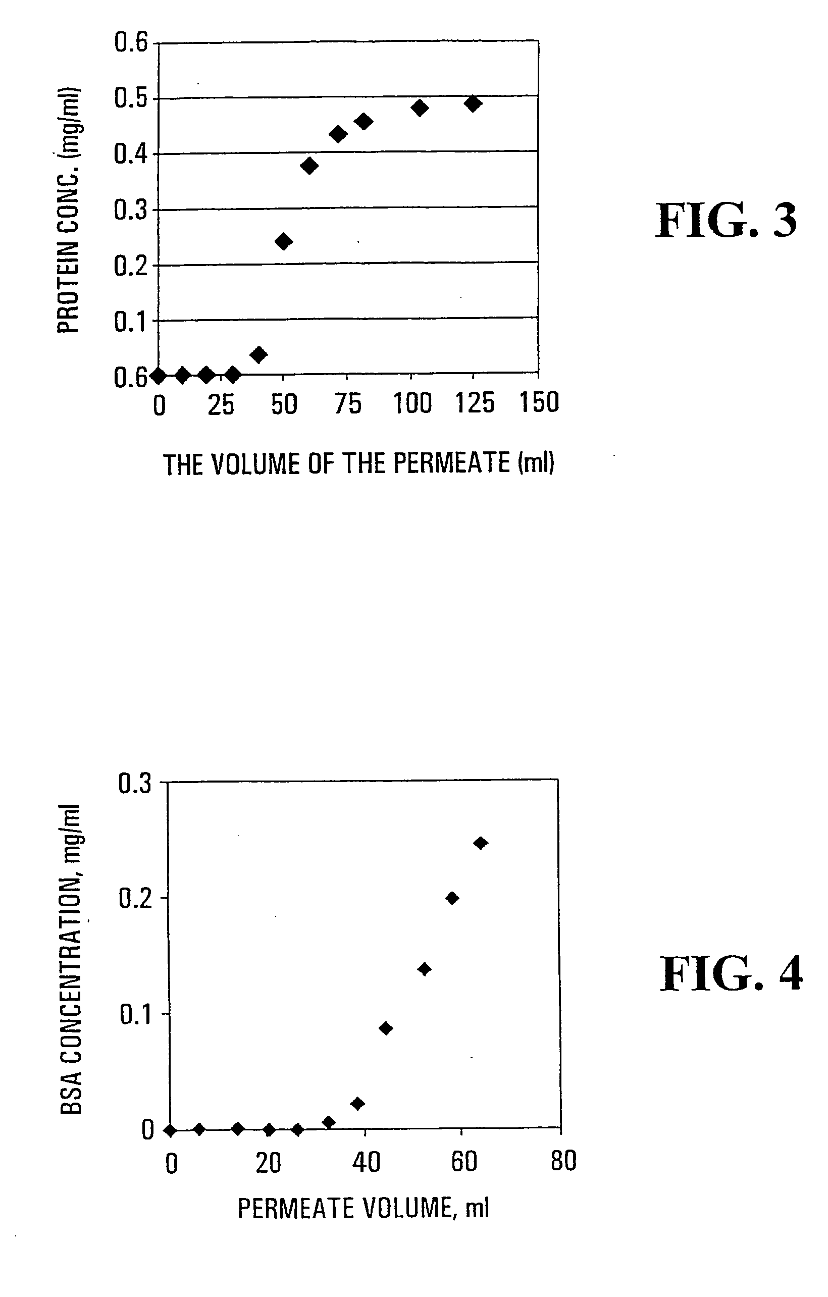
[0190]The protein (lysozyme) absorption / desorption characteristics of the composite material were ...


PUM

PropertyMeasurementUnit
Fractionaaaaaaaaaa
Fractionaaaaaaaaaa
Fractionaaaaaaaaaa

Abstract

This invention relates to a stable composite material comprising a support member that has a plurality of pores extending through the support member, and a macroporous crosslinked gel that is located in, and fills, the pores of the support member, in which crosslinked gel is entrapped a stabilising polymer, which stabilising polymer is neutral, linear or branched, non-crosslinked, and substantially water-insoluble. The presence of the stabilising polymer is such that it allows the composite material to largely retain its porosity and morphology after being dried. The invention also relates to a process for preparing the stable composite material described above, and to its use. The stable composite material is suitable, for example, for separation of substances, for example by filtration or adsorption, including chromatography, for use as a support in synthesis or for use as a support for cell growth.

Description

FIELD OF THE INVENTION[0001]This invention relates to a stable composite material comprising a supported macroporous crosslinked gel, which gel entraps a stabilising polymer.BACKGROUND OF THE INVENTION[0002]The combination of polymer chains and gels, commonly referred to as “snake-in-a cage” or “snake-cage” systems, has been reported previously, and such combinations have been used to achieve various purposes.[0003]In 1957, Hatch et al. disclosed a new type of ion-exchange resin, which they termed a snake-cage polyelectrolyte (Hatch et al., Industrial and Engineering Chemistry (1957), vol. 49, 1812-19). This compound consisted of a crosslinked polymer network carrying a fixed charge, in which was contained a physically trapped linear polyelectrolyte of the opposite charge. The crosslinked network used in this work was a commercial cationic resin, Dowex 1, constituting the “cage”, in which the linear anionic polymer “snake” was trapped. Amphoteric polymeric compositions prepared from...

Claims


Application Information

Patent Timeline
IPC IPC(8): B01J20/28B01J20/30B01D15/08B01D37/02B01J20/285B01J20/32B01J32/00C08J3/02C12N5/00G01N30/52
CPCB01J20/28033B01J20/28047B01J20/28078B01J20/28085B01J20/28097B01J20/285B01J20/32C12N5/0068C12N2533/30Y10S502/526B01J20/3204B01J20/321B01J20/3212B01J20/327B01J20/3282B01J20/3272B01J20/3278
Inventor MIKA, ALICJA M.WANG, MAGGIE SANJUCHILDS, RONALD F.
Owner MERCK MILLIPORE LTD
Learn More