Master cylinder and method of manufacturing the same
- Summary
- Abstract
- Description
- Claims
- Application Information
AI Technical Summary
Benefits of technology
Problems solved by technology
Method used
Image
Examples
first embodiment
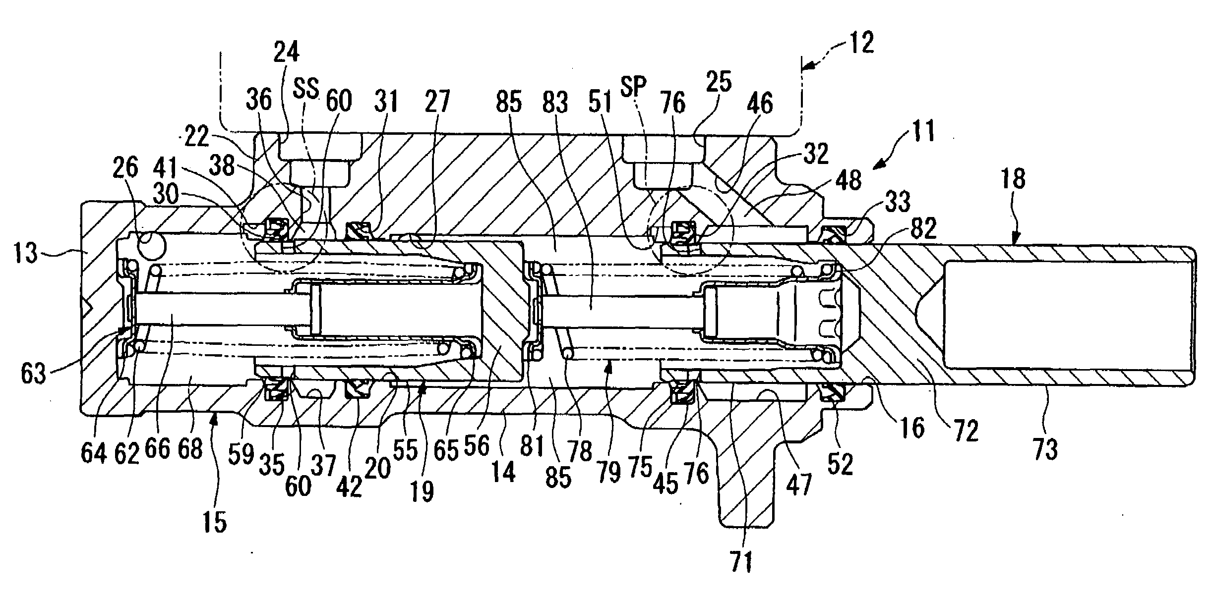
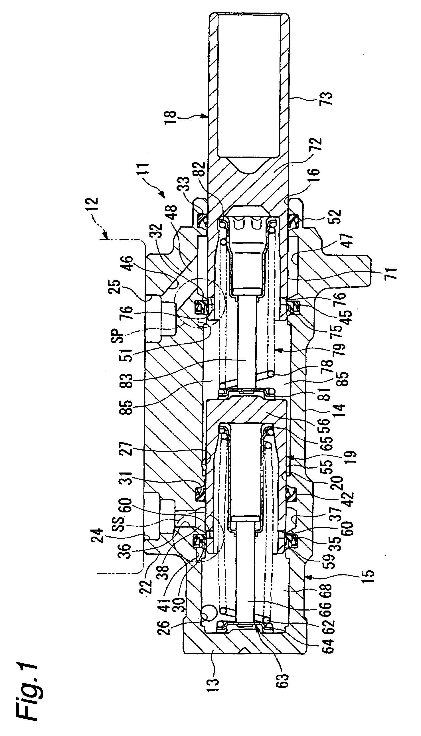
[0033]An explanation will be given of a master cylinder and a method for manufacturing the master cylinder according to the present invention in reference to FIG. 1 through FIG. 6.
[0034]A notation 11 in FIG. 1 designates a master cylinder of the first embodiment for generating a brake hydraulic pressure with a force according to an operation amount of a brake pedal introduced via a brake booster; though not shown, wherein a reservoir 12 for charging and discharging a brake fluid is mounted to an upper portion of the master cylinder 11.
[0035]The master cylinder 11 is of a tandem type, which comprises a cylinder main body 15 formed by processing a single mass of material into a bottomed cylinder shape having a bottom portion 13 and a cylinder portion 14, said cylinder main body 15 being arranged in a vehicle along a lateral direction, a primary piston (piston) 18 slidably inserted into the cylinder main body 15 in an opening portion 16 side thereof, and a secondary piston (piston) 19 ...
second embodiment
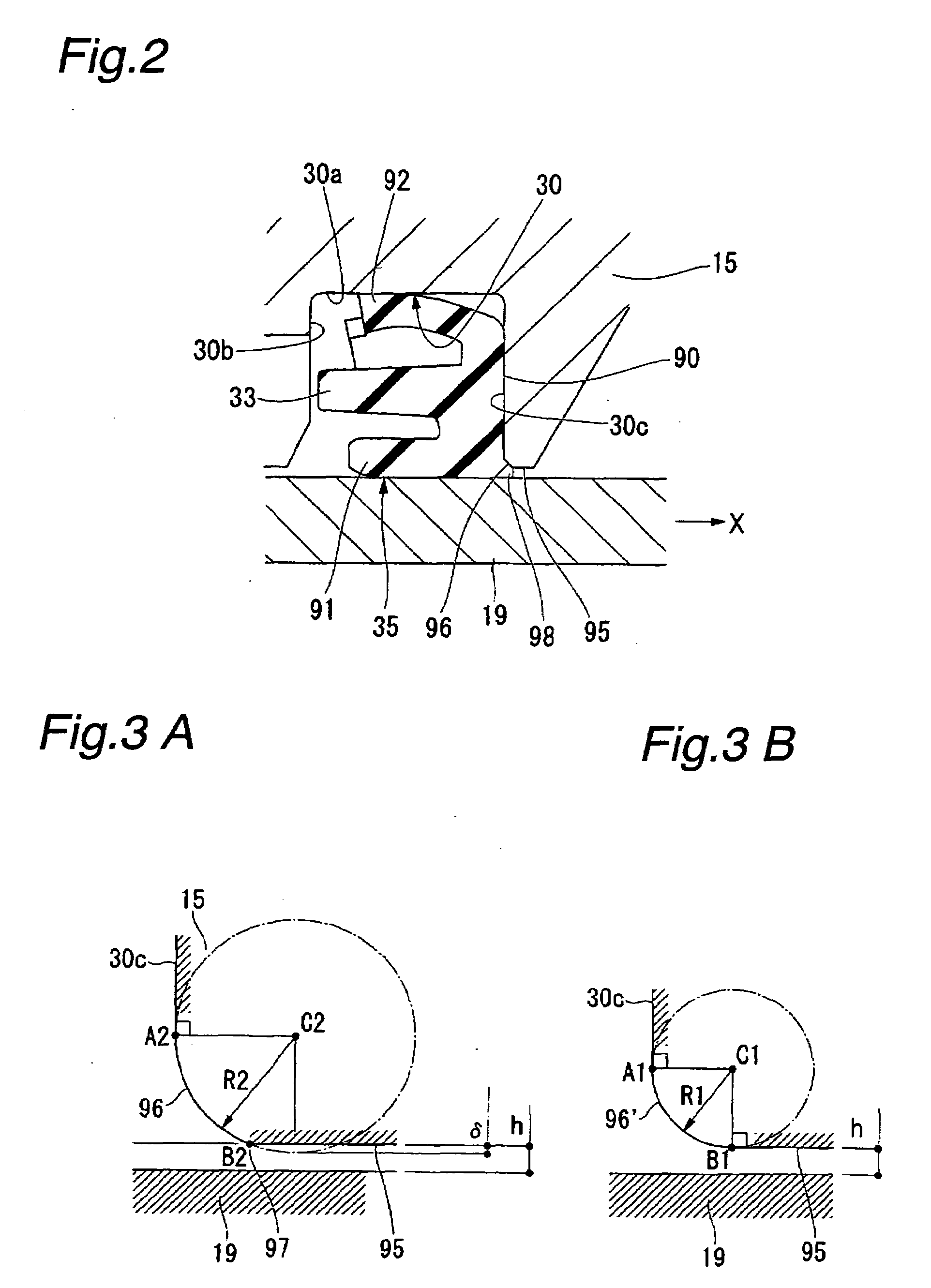
[0073] the secondary side sealing structure SS is provided with a chamfered portion 96 having a curved shape in a cross-section taken along the diameter direction of the cylinder main body 15 between the annular wall 30c and the cylinder wall 95, as shown in FIG. 7, wherein the chamfered portion 96 has a shape of an elliptic arc, a long axis of which extends along a radius direction of the cylinder main body 15.
[0074]The chamfered portion 96 is configured such that one end portion A2 is formed continuously so that a tangent thereof may be in line with a wall surface of the annular wall 30c, while the other end portion B2 is formed so as to constitute a flexed portion 97 in combination with the cylinder wall 95.
[0075]According to the master cylinder 11 of the second embodiment described above, in the secondary side sealing structure SS, since the chamfered portion 96 having a shape of an elliptic arc and formed between the annular wall 30c behind the cup seal 35 and the cylinder wall...
third embodiment
[0080] the secondary side sealing structure SS is provided with a chamfered portion 96 having a curved shape in a cross-section taken along the diameter direction of the cylinder main body 15 between the annular wall 30c and the cylinder wall 95, wherein the chamfered portion 96 has a shape of a parabola, and is connected to the annular wall 30c at a vertex of the parabola shape.
[0081]The chamfered portion 96 is configured such that one end portion A2 is formed continuously so that a tangent thereof may be in line with a wall surface of the annular wall 30c, while the other end portion B2 is formed so as to constitute a flexed portion 97 in combination with the cylinder wall 95.
[0082]According to the master cylinder 11 of the third embodiment described above, in the secondary side sealing structure SS, since the chamfered portion 96 having a shape of a parabola and formed between the annular wall 30c behind the cup seal 35 and the cylinder wall 95 to which the secondary piston 19 is...
PUM
 Abstract
Description
Claims
Application Information
 - R&D
- Intellectual Property
- Life Sciences
- Materials
- Tech Scout
- Unparalleled Data Quality
- Higher Quality Content
- 60% Fewer Hallucinations
Browse by: Latest US Patents, China's latest patents, Technical Efficacy Thesaurus, Application Domain, Technology Topic, Popular Technical Reports.
© 2025 PatSnap. All rights reserved.Legal|Privacy policy|Modern Slavery Act Transparency Statement|Sitemap|About US| Contact US: help@patsnap.com


