
Pneumatic tire

A pneumatic tire, tire circumferential technology, applied in tire parts, tire tread/tread pattern, transportation and packaging, etc., can solve the problems of reducing the durability of pattern blocks, easy to generate cracks, poor grip, etc., to achieve Effects of suppressing cracks, alleviating stress concentration, and suppressing reduction in grip

Inactive Publication Date: 2012-01-25
SUMITOMO RUBBER IND LTD
View PDF5 Cites 13 Cited by
  • Summary
  • Abstract
  • Description
  • Claims
  • Application Information

AI Technical Summary

Problems solved by technology

Although such a sipe can prevent openings, compared with the elongated sipe b, since the length of the edge component is reduced, the grip on icy and snowy roads is poor
In addition, when the inner ends c1 and c1 are approached to suppress the reduction in the length of the edge components, there is a problem that stress is concentrated at the inner end c1 and cracks are likely to occur, thereby reducing the durability of the block.

Method used


Image

  • Pneumatic tire
  • Pneumatic tire
  • Pneumatic tire

Examples


Embodiment Construction

[0028] Next, embodiments of the present invention will be described in detail.

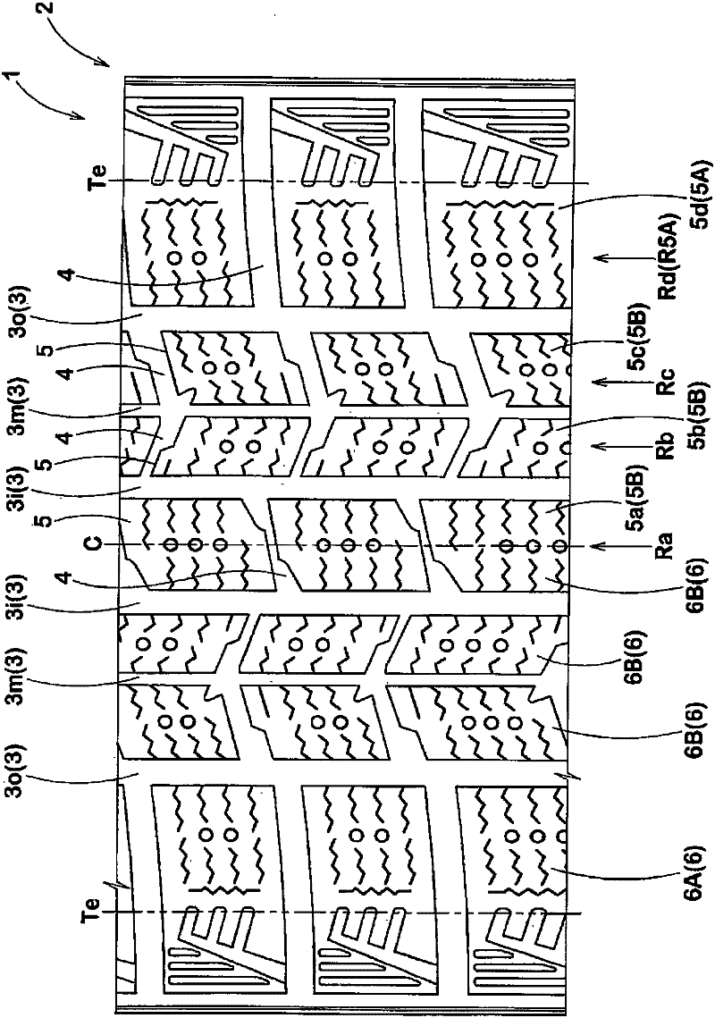
[0029] figure 1 In the pneumatic tire 1 of this embodiment, the tread portion 2 has a circumferential groove 3 extending in the tire circumferential direction, and between the circumferential grooves 3, 3 and / or between the circumferential groove 3 and the tread edge Te. The extended lateral groove 4 thereby forms a plurality of blocks 5 defined by the circumferential groove 3 and the lateral groove 4 , or the circumferential groove 3 and the tread edge Te and the lateral groove 4 in the tread portion 2 .

[0030] In addition, the plurality of blocks 5 include: a shoulder block 5A forming a shoulder block row R5A extending in the tire circumferential direction along the tread edge Te; The shoulder block 5A is closer to the inner side in the tire axial direction (the tire equator plane side).

[0031] Specifically, the pneumatic tire 1 of this example is formed with a total of six circumferentia...


PUM


Abstract

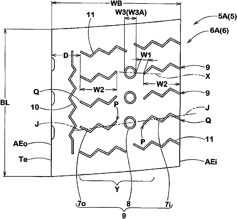
The invention provides a pneumatic tire, which can inhibit a crack generated at the inner side terminal of a blade groove pattern. The decrease of the edge length can prevent an opening. A plurality of pattern areas are provided on the surface of the pneumatic tire. The pattern areas at least include the following: a pattern area with an annular blade groove possessing a blade groove assembly, the blade groove assembly includes a pair of blade groove pattern plates, which are extended respectively from the two-side pattern blocks at the pattern area width direction inward; and annular blade groove patterns which are arranged between the inner sides.

Description

technical field [0001] The invention relates to a pneumatic tire suitable for traveling on ice and snow roads. Background technique [0002] Pneumatic tires suitable for driving on icy roads, such as studless tires, such as Figure 8 (A) As schematically shown, a plurality of sipe b is formed on the block a provided on the tread portion, and the frictional force is improved by utilizing the road surface gripping effect (edge ​​effect) generated by the edge thereof, and the sipe b is improved on the ice and snow road surface. excellent braking performance and traction performance. [0003] In addition, in order to further increase the frictional force by increasing the length of the edge components of the sipe b, as shown in the above-mentioned figures, conventionally, the sipe b extending across the block a along the tire axial direction has been widely used. The long strip of sipe b. However, in such a long sipe b, such as Figure 8 (B) As shown exaggeratedly, there is a ...

Claims


Application Information

Patent Timeline
Patent Type & Authority Applications(China)
IPC IPC(8): B60C11/13
CPCB60C11/11B60C11/1204B60C11/1236B60C2011/1268
Inventor 高桥伸吾
Owner SUMITOMO RUBBER IND LTD
Learn More