Flexure and method of forming part of flexure
a technology of flexure and wiring part, which is applied in the direction of photomechanical equipment, instruments, and photosensitive material processing, etc., can solve the problems of inability to reduce the rigidity contribution ratio of the wiring part, and the difficulty of controlling the rigidity around the tongue of the flexure, etc., and achieves low rigidity contribution ratio
- Summary
- Abstract
- Description
- Claims
- Application Information
AI Technical Summary
Benefits of technology
Problems solved by technology
Method used
Image


Examples
first embodiment
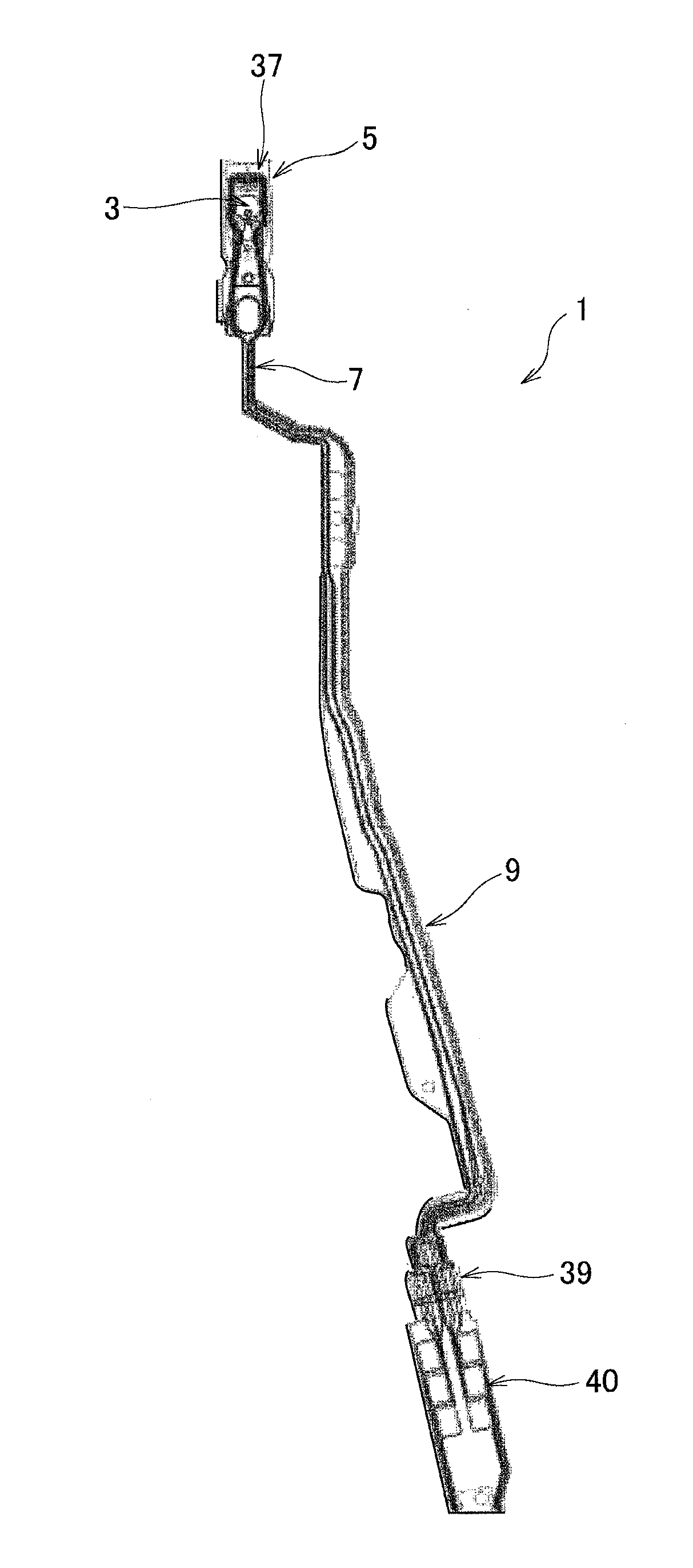
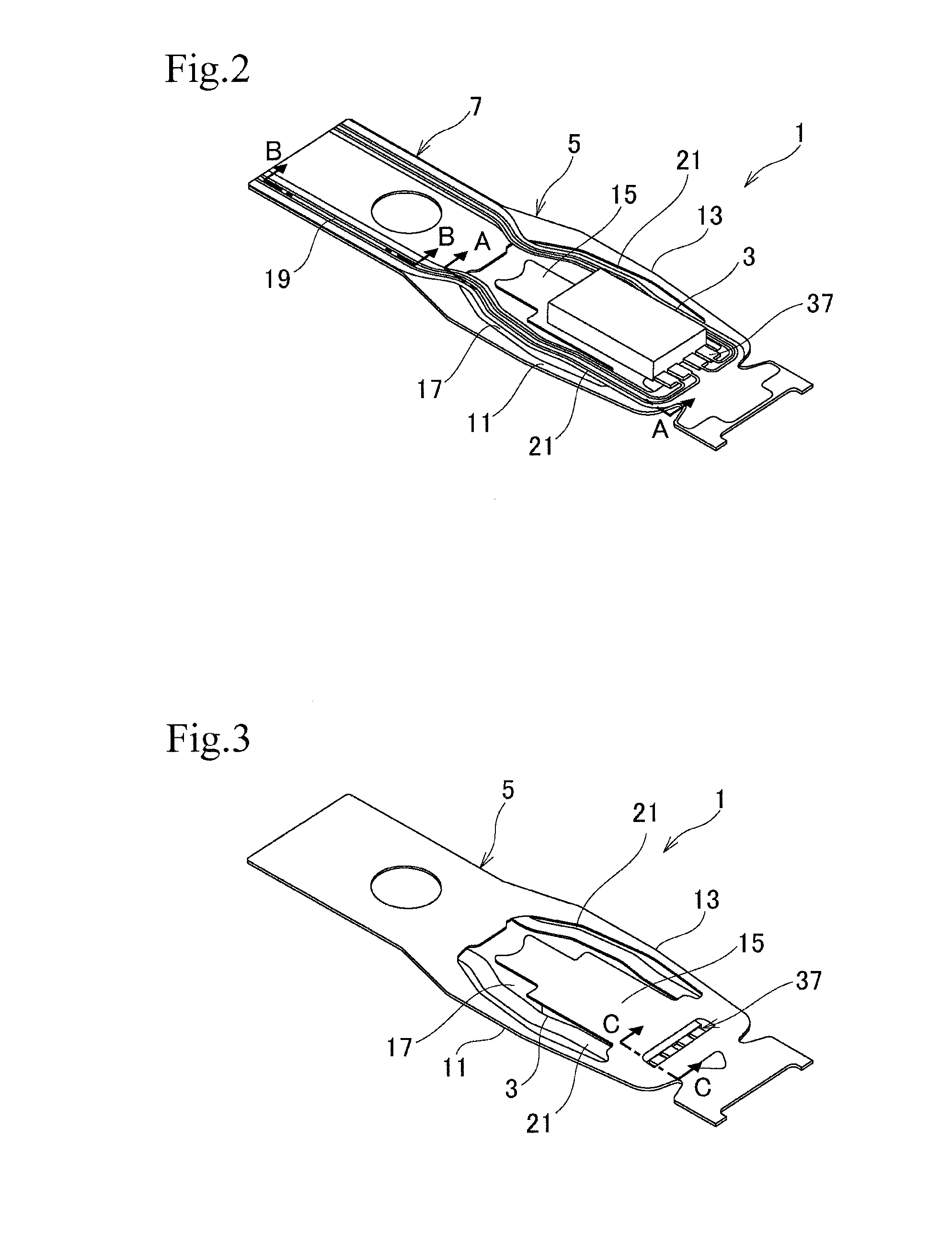
[0036]A general configuration of a flexure according to the present invention will be explained with reference to FIGS. 1 to 6. FIG. 1 is a plan view generally illustrating the flexure, FIG. 2 is an enlarged perspective view illustrating a top surface of a part of the flexure of FIG. 1, FIG. 3 is an enlarged perspective view illustrating a bottom surface of the part illustrated in FIG. 4 is a plan view illustrating the part illustrated in FIG. 2, FIG. 5 is a bottom view of the part illustrated in FIG. 4, and FIG. 6 is an enlarged perspective view illustrating an end of a tail part of the flexure illustrated in FIG. 1.
[0037]The flexure 1 illustrated in FIG. 1 is attached to a load beam of a head suspension that is installed in, for example, a hard disk drive of a personal computer. A front end of the flexure 1 supports a slider 3 that is used to write and read data to and from a hard disk in the hard disk drive.
[0038]As illustrated in FIGS. 1 to 6, the flexure 1 has a metal substrate...
second embodiment
[0116]A method of forming the wiring part 7A of the flexure 1A will be explained with reference to FIGS. 15A and 15B in which FIGS. 15A and 15B are sectional views illustrating forming the aerial wiring part 21A.
[0117]The aerial wiring part 21A is formed through the base forming step, conductor layer forming step, cover forming step, space forming step, and second recess forming step selected from among the terminal forming steps of the first embodiment.
[0118]In FIG. 15A, the base forming step forms the base insulating layer 23A on the metal substrate 5.
[0119]The first recess forming step is carried out only on the terminals 37 and 39 and is not carried out on the aerial wiring part 21A. Omitting the first recess forming step from the aerial wiring part 21A is realized by adjusting the pattern of a gradation mask. Namely, the gradation mask is provided with an exposure amount adjustable pattern reducing the exposure amount at locations where the terminals 37 and 39 are formed, or a...
third embodiment
[0132]FIG. 17 is an enlarged perspective view illustrating a top surface of a part of the flexure FIG. 18 is a plan view illustrating the part illustrated in FIG. 17, and FIG. 19 is a bottom view of the part illustrated in FIG. 18.
[0133]Unlike the first and second embodiments that employ the aerial wiring part 21 (21A) passing through or being on the gap 17 between the tongue 15 and the outriggers 11 and 13, the third embodiment employs an aerial wiring part 21B that passes through or is on a space outside outriggers 11B and 13B as illustrated in FIGS. 17 to 19.
[0134]A wiring part 7B of the third embodiment extends from a fixed end of a tongue 15B and runs outside the outriggers 11B and 13B across them.
[0135]Outside the outriggers 11B and 13B, the wiring part 7B forms the aerial wiring part 21B that passes through or is on the outside space. The aerial wiring part 21B extends in parallel with the outriggers 11B and 13B. The aerial wiring part 21B is formed according to the wiring p...
PUM
 Abstract
Description
Claims
Application Information
 - R&D
- Intellectual Property
- Life Sciences
- Materials
- Tech Scout
- Unparalleled Data Quality
- Higher Quality Content
- 60% Fewer Hallucinations
Browse by: Latest US Patents, China's latest patents, Technical Efficacy Thesaurus, Application Domain, Technology Topic, Popular Technical Reports.
© 2025 PatSnap. All rights reserved.Legal|Privacy policy|Modern Slavery Act Transparency Statement|Sitemap|About US| Contact US: help@patsnap.com