
Programmable Logic Array for Schedule-Controlled Processing

a logic array and schedule control technology, applied in special data processing applications, instruments, electric digital data processing, etc., can solve the problems of difficult access to internal nodes, difficult consulting and modification, and hardly predictive

Inactive Publication Date: 2008-10-23
GASOLINELI JEAN PAUL
View PDF2 Cites 0 Cited by
  • Summary
  • Abstract
  • Description
  • Claims
  • Application Information

AI Technical Summary

Benefits of technology

[0035]the unit time control avoids the emulation of a delay or additional clock and makes easier the design of the function to emulate;
[0037]the synchronous aspect avoids re-synchronization needs between asynchronous clocks in the classical array case.
[0040]while the circuit is in operation, the basic access to the nodes for external consultation or change is easy and without re-programming; and
[0041]the flow chart, without placement and routing constraints, is simpler to design and implement.
[0049]Thanks to these facilities, the time relationship between the data processing is simpler to design and manage.

Problems solved by technology

This kind of programmable array has the following disadvantages:it does not make any distinction between the frequently activated parts and the less frequently activated parts;it controls, with difficulty, the timing of the state change of the node, indeed it is complex and hardly predictive;it needs a complex flow of tools: logic synthesizer, mapper and router, being expensive in the design phase;it makes access to internal nodes difficult (consulting and modifying) otherwise than by re-programming the device;it generates problems of excessive load of the line;it generates operating problems in case of several clocks; andit provides many inactivated resources with leakage current which results in significant useless power consumption for all of the circuit.

Method used


Image

  • Programmable Logic Array for Schedule-Controlled Processing
  • Programmable Logic Array for Schedule-Controlled Processing
  • Programmable Logic Array for Schedule-Controlled Processing

Examples


Embodiment Construction

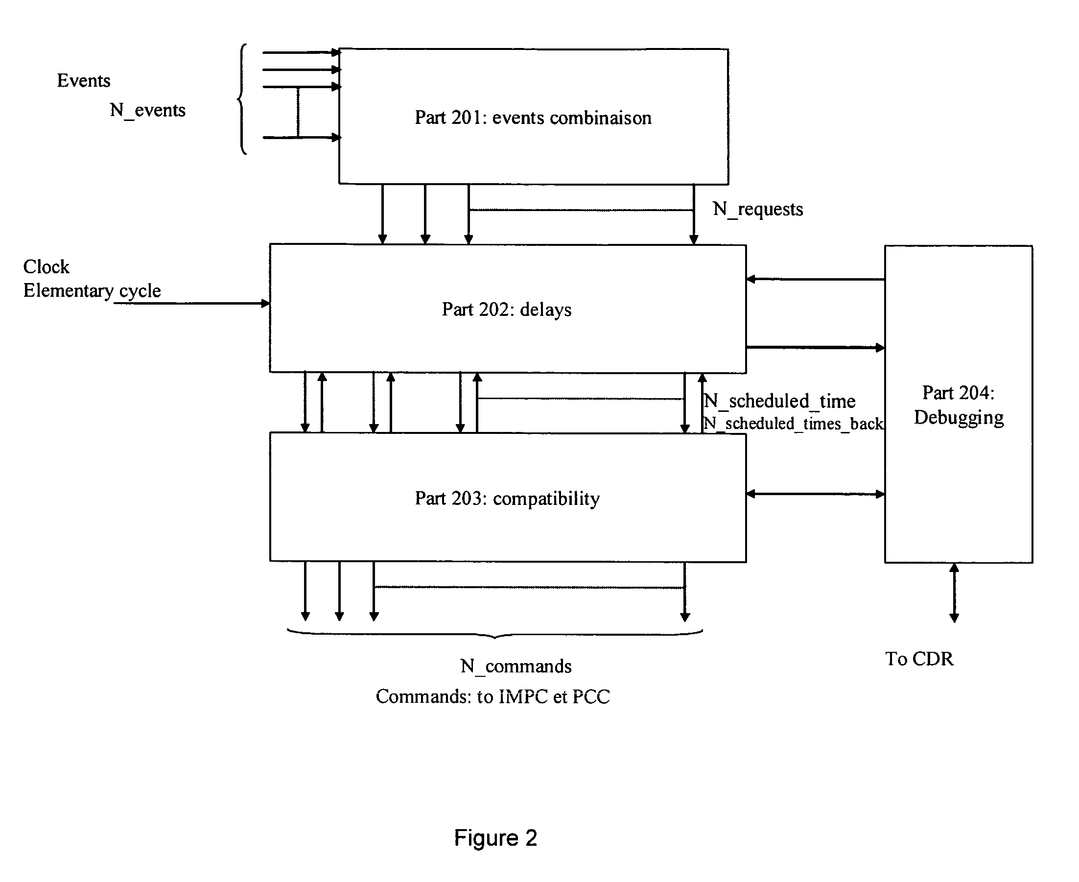
[0078]Before describing the figures, a general description of the electronic circuit, including the object of the present invention, is given in several parts:[0079]a scheduler which is the core;[0080]an N_IMPC array: Internal Memorization and Processing Cell;[0081]a N_PCC array: Peripheral Communication Cell;[0082]a connecting values link array between cells;[0083]a loading dedicated cell part at the programming time called Central Programming Resource CPR; and[0084]a reading and modifying dedicated part for stored data in IMPC, and PCC is called Central Debugging Resource.

[0085]FIG. 1 describes a simplified architecture of an electronic circuit according to the present invention. Inside this architecture, a scheduler 100 has the following functions:[0086]to accept as input the primary information of logic states changes provided by the cell IMPC 111 to 132 and PCC 101 to 108;[0087]to combine these information to requests according to the user programming;[0088]to schedule events a...


PUM


Abstract

The electronic data processing circuit targets the emulation of a logic function. The circuit includes a single clock providing time unit signals, a programmable synchronous logic array for processing values on a time unit basis, detection of internal or external value state changes known as events, programmer for state changes or event signals, processor for a series of scheduled times providing the logic array with scheduled time signals depending on the signals from the detection or the event programmer and the signals from the clock. The processor can determine subsequent scheduled times having delayed deadlines programmed by the programmer, depending on the signals from the detection or the programmer. The processing performed by the logic array is thus dependent on the series of scheduled times triggered by internal or external value state changes and by determination of the series of scheduled times.

Description

RELATED U.S. APPLICATIONS[0001]Not applicable.STATEMENT REGARDING FEDERALLY SPONSORED RESEARCH OR DEVELOPMENT[0002]Not applicable.REFERENCE TO MICROFICHE APPENDIX[0003]Not applicable.FIELD OF THE INVENTION[0004]This invention relates to a programmable logic array with processing facilities relying on a scheduler. It applies to a complex logic function emulation device triggered by an internal or external event.BACKGROUND OF THE INVENTION[0005]Inside the state of art for programmable arrays, the logical function to be emulated is divided into elementary logic functions. An interconnection array made of programmable links connects the overall whole of cells in order to propagate any change of logic state towards the concerned elementary functions.[0006]The programming of this kind of array is static (static array). The programming remains unchanged while the complex function is running.[0007]The programming is generally the result of the placer and router software, with the support of...

Claims


Application Information

Patent Timeline
Patent Type & Authority Applications(United States)
IPC IPC(8): G06F17/50H03K19/177
CPCH03K19/177H03K19/17704
Inventor PETROLLI, JEAN PAUL
Owner GASOLINELI JEAN PAUL
Learn More