
Alkaline-resistant negative photoresist for silicon wet-etch without silicon nitride

Active Publication Date: 2008-10-23
BREWER SCI
View PDF18 Cites 11 Cited by
  • Summary
  • Abstract
  • Description
  • Claims
  • Application Information

AI Technical Summary

Benefits of technology

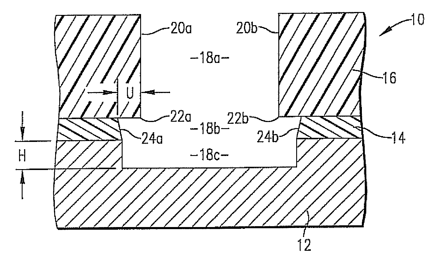
[0006]The present invention overcomes these problems by providing spin-applied, photosensitive coating systems that replace prior art masks or protective coatings, and that eliminate the need for additional photoresists in the system. The inventive systems protect device features from corrosion and other forms of attack during deep-etching processes that utilize concentrated aqueous bases.

Problems solved by technology

However, this can only be carried out after the protective coating or mask has been applied, thus requiring time and expense to apply and later etch this protective layer or mask, which is very difficult to remove.

Method used


Image

  • Alkaline-resistant negative photoresist for silicon wet-etch without silicon nitride
  • Alkaline-resistant negative photoresist for silicon wet-etch without silicon nitride
  • Alkaline-resistant negative photoresist for silicon wet-etch without silicon nitride

Examples


example 1

Primer Solution Formulation

[0066]To prepare a primer solution, 2.04 g of N-phenylaminopropyl-trimethoxysilane (obtained from Gelest, Morrisville, Pa.) were dissolved in a mixture of 77.50 g of propylene glycol propyl ether (PnP; obtained from General Chemical, Parsippany, N.J.), 120.14 g of deionized water, 0.51 g of acetic acid (obtained from Aldrich, Milwaukee, Wis.), and 0.03 g of FC-4430 (a surfactant, obtained from 3M, St. Paul, Minn.). The solution was stirred magnetically for more than 2 hours. It was then filtered through a 0.1-μl membrane filter.

example 2

Copolymer Solution Preparation

[0067]A copolymer solution was made by dissolving 150.1 g of polystyrene-co-polyacrylonitrile copolymer (obtained from Bayer USA, Pittsburgh, Pa.) in a mixture of 595.0 g of propylene glycol methyl ether acetate (PGMEA; obtained from General Chemical, Parsippany, N.J.) and 255.0 g of ethyl acetoacetate (EAA; obtained from Harcros, Kansas City, Kans.).

example 3

Photoacid Generator Solution Preparation

[0068]A photoacid generator (PAG) solution was made by dissolving 60.02 g of UVI-6976 (obtained from Dow Chemical, Midland, Mich.) in 140.08 g of PGMEA.


PUM

PropertyMeasurementUnit
Fractionaaaaaaaaaa
Fractionaaaaaaaaaa
Fractionaaaaaaaaaa

Abstract

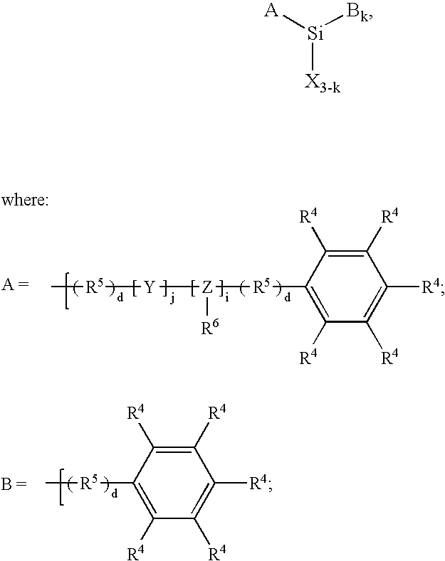
New photoresists for use during the production of semiconductor and MEMS devices are provided. The primer layer preferably comprises a silane dissolved or dispersed in a solvent system. The photoresist layer includes a first polymer prepared from a styrene and an acrylonitrile, and a second polymer comprising epoxy-containing monomers (and preferably phenolic-containing monomers). The photoresist layer comprises a photoacid generator, and is preferably negative-acting.

Description

BACKGROUND OF THE INVENTION[0001]1. Field of the Invention[0002]The present invention is concerned with new photoresists for use in the manufacture of microelectronic devices such as those used in microelectromeclanical systems (MEMS).[0003]2. Description of the Prior Art[0004]It is common in silicon etching processes to utilize a thin (100- to 300-nm) silicon nitride or silicon dioxide coating on the silicon substrate as a mask for patterned etching or as a passivating layer to enclose active circuitry. In the prior art, etch protective coatings or masks for MEMS fabrication processes have been selected primarily by using a trial-and-error method because there are no general purpose protective coatings on the market. The etch selectivity of the etchants to various materials is often used as a guide for MEMS process engineers. With a much lower etch rate than silicon, films of silicon nitride have been used as a protective layer or hardmask during KOH or TMAH bulk silicon etching. S...

Claims


Application Information

Patent Timeline
IPC IPC(8): G03C1/043G03C5/00
CPCG03F7/0045G03F7/0382Y10S430/115G03F7/0752Y10S430/108G03F7/0751G03F7/004G03F7/038
Inventor ZHONG, XING-FUFLAIM, TONY D.MALHOTRA, JYOTI
Owner BREWER SCI
Learn More