RFID tag
a radio frequency identification and tag technology, applied in the field of rfid (radio frequency identification) tags, can solve the problems of rfid tags being likely to fall off the surface of metal materials, the entire rfid tag becoming thicker, etc., and achieves the effect of reducing the influence of the plane of polarization of the receiving antenna, and reducing the change in communication distan
- Summary
- Abstract
- Description
- Claims
- Application Information
AI Technical Summary
Benefits of technology
Problems solved by technology
Method used
Image
Examples
first embodiment
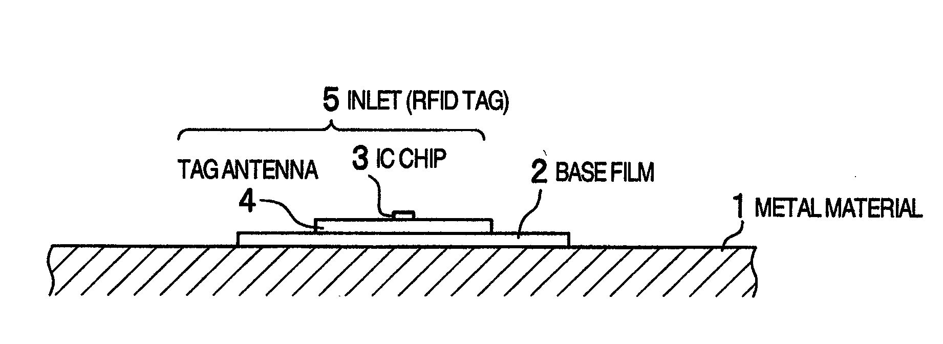
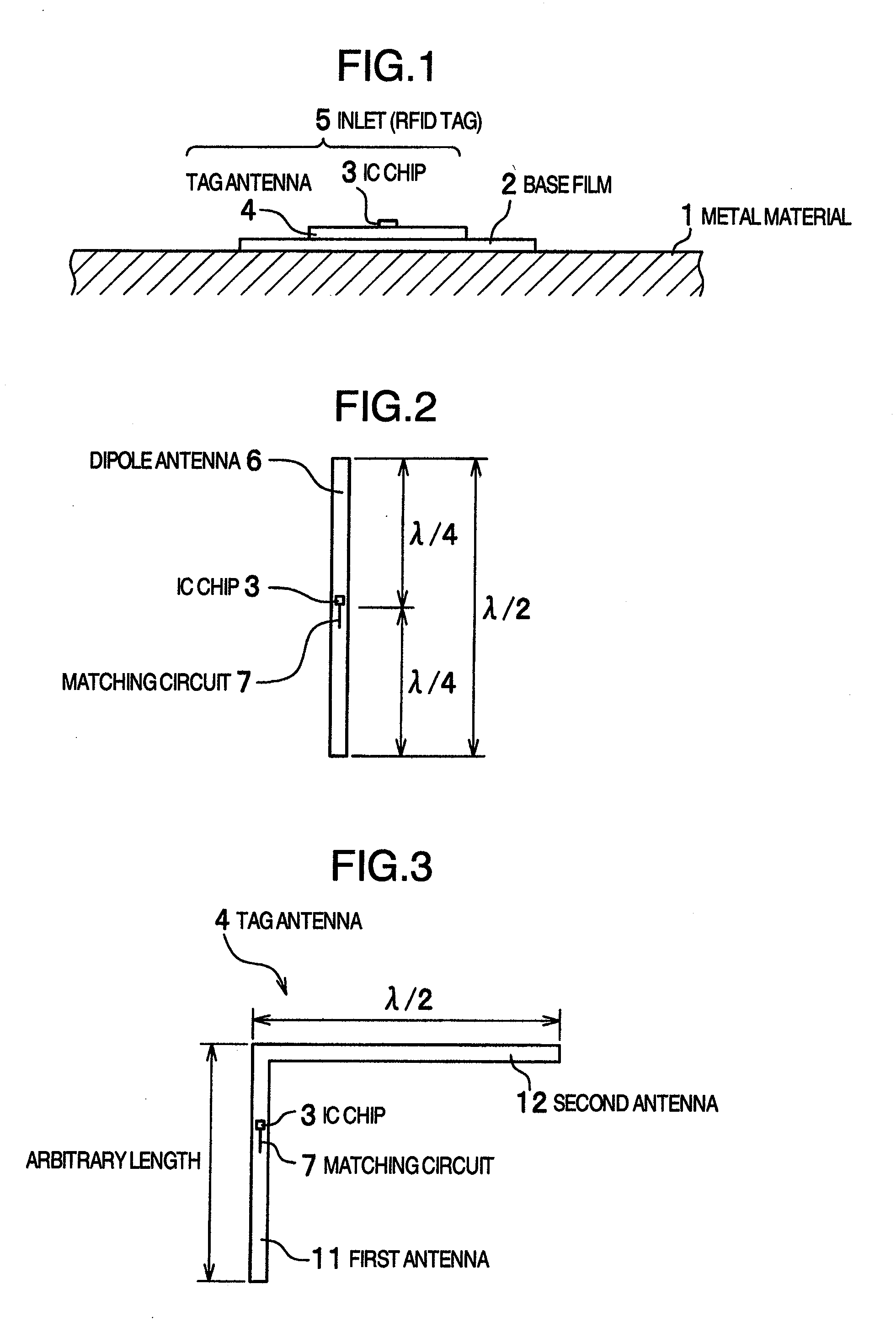
[0034]Embodiments of an RFID tag according to the present invention will be described below in detail with reference to the accompanying drawings. FIG. 1 is a cross-sectional view of an RFID tag attached to a surface of a metal material. A tag antenna 4 having an IC chip 3 mounted thereon (hereinafter an arrangement including the IC chip 3 and the tag antenna 4 is referred to as an inlet 5 and an arrangement laminated with an outer film or films, not shown, is referred to as an RFID tag) is attached to a surface of a resin base film 2 by an adhesive or the like. The base film 2, which acts as a spacer, is placed between the surface of a metal material 1 and the tag antenna 4. Thus, information recorded on the IC chip 3 can be read and written by a reader / writer (not shown) when the reader / writer is passed near the tag antenna 4.
[0035]FIG. 2 is a top view showing an RFID tag that uses a dipole antenna as the tag antenna 4 shown in FIG. 1. The dipole antenna 6 has an electrical length...
second embodiment
[0060]Several variations of the strip tag antenna have been described in the first embodiment. Several variations of a wide tag antenna having a wide second antenna will be described in a second embodiment.
First Variation of Wide Tag Antenna
[0061]FIG. 12 is a configuration diagram of a first variation of a wide tag antenna according to the second embodiment. In this variation, the configuration of the first variation of the first embodiment shown in FIG. 3 is modified to increase the width of the second antenna. That is, as shown in FIG. 12, a longer side of a rectangular second antenna 22 wider than a first antenna 21 having an IC chip 3 mounted thereon is connected to an end of the first antenna 21. The second antenna 22 extends in a direction at right angles to the first antenna 21. The first antenna 21 has an arbitrary length. The wide second antenna 22 extending from the end of the first antenna 21 at right angles has an electrical length of λ / 2 or λ / 2 multiplied by n (where n ...
third embodiment
[0070]In a third embodiment, a detailed description will be given of an embodiment in which a tag antenna is formed on a base film, an embodiment in which a first antenna is electrically coupled with a second antenna, and an embodiment in which an inlet formed by a tag antenna on which an IC chip is mounted is laminated with a protective film to form an RFID tag.
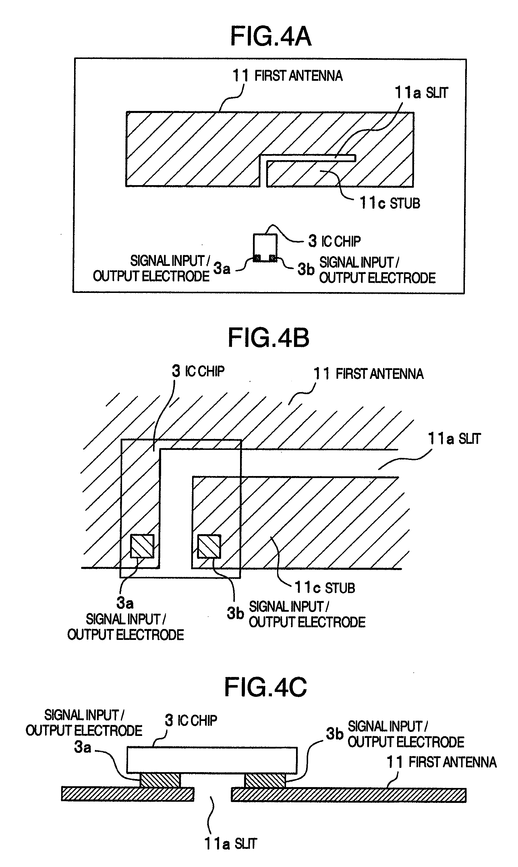
[0071]FIG. 18 is a conceptual diagram of one embodiment, viewed from above, in which a tag antenna is formed on a base film according to the third embodiment. First and second antennas 21 and 22 each having a thickness of on the order of several tens of μm are contiguously deposited by metal vapor deposition or formed of a metal foil on a base film 2 made of a heat-resistant polyimide film having a thickness of approximately 30 μm, for example. Then, a slit is formed in a predetermined position on the first antenna 21, a matching circuit 7 is provided, and an IC chip 3 is mounted on it. A tag antenna 4 is thus formed, where ...
PUM
 Abstract
Description
Claims
Application Information
 - R&D
- Intellectual Property
- Life Sciences
- Materials
- Tech Scout
- Unparalleled Data Quality
- Higher Quality Content
- 60% Fewer Hallucinations
Browse by: Latest US Patents, China's latest patents, Technical Efficacy Thesaurus, Application Domain, Technology Topic, Popular Technical Reports.
© 2025 PatSnap. All rights reserved.Legal|Privacy policy|Modern Slavery Act Transparency Statement|Sitemap|About US| Contact US: help@patsnap.com


