Eureka AIR delivers breakthrough ideas for toughest innovation challenges, trusted by R&D personnel around the world.

Microbial Biocementation

a biocementation and microorganism technology, applied in soil conditioning compositions, solid waste management, sustainable waste treatment, etc., can solve the problems of insufficient strength of cement, insufficient degree of control of process, and particularly useful, so as to increase the resistance of offshore structures, reduce dust levels, and increase the resistance to petroleum borehole degradation

Active Publication Date: 2008-10-09
DUST BIOSOLUTIONS GMBH
View PDF1 Cites 35 Cited by
  • Summary
  • Abstract
  • Description
  • Claims
  • Application Information

AI Technical Summary

Benefits of technology

[0007]The method of the present invention can form high strength cement through the production of relatively high levels of calcite in the starting material. Thus, the present invention also provides a method of forming a high strength cement in a permeable starting material, the method comprising the step of combining the starting material with effective amounts of (i) a urease producing micro-organism; (ii) urea; and (iii) calcium ions and wherein the cement results from the formation of at least 33 g of calcite per litre of material added to the starting material.
[0011]One of the advantages of the present invention is that it may be applied without unnecessary disruption or disturbance of the starting material. Thus, the present invention also provides an in situ method of forming a high strength cement in a permeable starting material, the method comprising the step of combining the starting material with effective amounts of (i) a urease producing micro-organism; (ii) urea; and (iii) calcium ions and wherein the effective amount of the urease producing organism provides a urea hydrolysis rate, under standard conditions, of 0.5-50 mM urea hydrolysed.min−1.
[0013]The present invention may be applied to produce cement for use in applications in civil engineering, mining, erosion control, environmental and the manufacture of special materials. Ground improvement applications are particularly suited for the present invention. Civil engineering applications include application of the method to retaining walls, embankments (e.g. railway embankments, dams) and ground for tunnelling to reinforce and stabilise soil; foundations to improve skin friction of piles (bonding them to the “far field”); increasing the end-bearing capacity of piles; stiffening in situ formation to reduce pile design lengths; improving the bearing capacity of soils for non-piled foundations; and the stabilisation of sands in earthquake zones at risk of liquefaction.
[0016]Uses in the mining industry include the use of the method to provide support to broken ground during tunnelling and mining; strengthen tailings dams to prevent erosion and slope failure; provide a permeable reactive barrier to allow drainage and remove acidic and heavy metal discharges from mines; bind dust particles on exposed surfaces to reduce dust levels; increase resistance to petroleum borehole degradation during drilling and extraction; increase the resistance of offshore structures to erosion of sediment within or beneath gravity foundations and pipelines.
[0017]The method of the present invention also has environmental applications such as the stabilisation and removal of pollutants (e.g. heavy metals, fibres, radioactive elements) from the environment by binding them into the calcite crystal structures and the control of erosion in coastal area and rivers by strengthening exposed surfaces and thus protecting areas subject to erosion.

Problems solved by technology

However, whilst these plugs have been used to reduce the porosity / permeability of fissures and other cracks in geological formations, the resulting cement is not strong enough for a range of other applications.
Furthermore, the degree of control of the process used to form mineral plugs is limited meaning that results are inconsistent and there are many applications where the method is simply not viable.
Conventional cement is used for a variety of structural applications However, because conventional cement is applied as a fairly thick slurry, it is not adapted for spray application nor is it particularly useful for applications where it is necessary or desirable to form the cement at or below a surface or retain the porosity of the cemented material.

Method used


Image

  • Microbial Biocementation
  • Microbial Biocementation
  • Microbial Biocementation

Examples


example 1

Biocementation in Si-Sand

[0113]Materials & Methods

[0114](A) Application of Cementation Reactants into the Core

[0115]Cores for cementation consisted of 50 ml plastic syringes that were dry packed with 300 μm Si-sand under continuous vibration to give an even density. Cores were then up-flushed with water and tapped to remove air pockets. After flushing with water, the volume occupied by the sand decreased due to the lubrication effect between the sand particles and the stopper was adjusted to maintain a confining pressure.

[0116]Ca / urea solution and cells were premixed immediately before injection into the core by pouring both liquids into a single vessel and twice drawing and expelling the liquid with a second 50 ml syringe, to ensure proper mixing. One and a half times the pore volume was flushed in to ensure full displacement of water.

[0117](B) In-situ Cementation Measurements

[0118]Strength was measured by sending ultrasound waves through the diameter of each core at three position...

example 2

Biocementation in Other Sands

[0150]Materials & Methods

[0151](A) Vegemite Acetate Medium

[0152]Vegemite acetate medium consisted of 13.5 g.L−1 Vegemite, from which the solids were removed by gravity settling followed by decanting the upper fraction and 150 mM acetate added as glacial acetic acid. The pH was adjusted to 7 with 6 M NaOH.

[0153]For the inoculum cultivation, the medium was sterilised and 10 g.L−1 urea was added by sterile filtration, post-sterilisation. For the pilot-scale cultivation, the medium was not sterilised and urea was added without sterile filtration.

[0154](B) 10 L Pilot-Scale Inoculum Cultivation

[0155]A pilot-scale inoculum was grown under sterile conditions in a 10 L stirred tank reactor (Chemap, Germany), at 30° C. with a starting pH of 8.25.

[0156](C) 100 L Pilot-Scale Cultivation

[0157]The pilot-scale cultivation was conducted under non-sterile conditions in a 120 L custom-built fibreglass airlift reactor (courtesy of Andrew Brown & Co., Perth), with a working...

example 3

Enhancing Penetration Depth for Biocementation

[0179]Materials / Methods

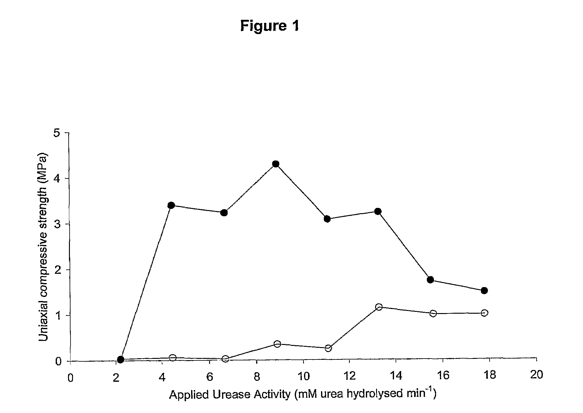
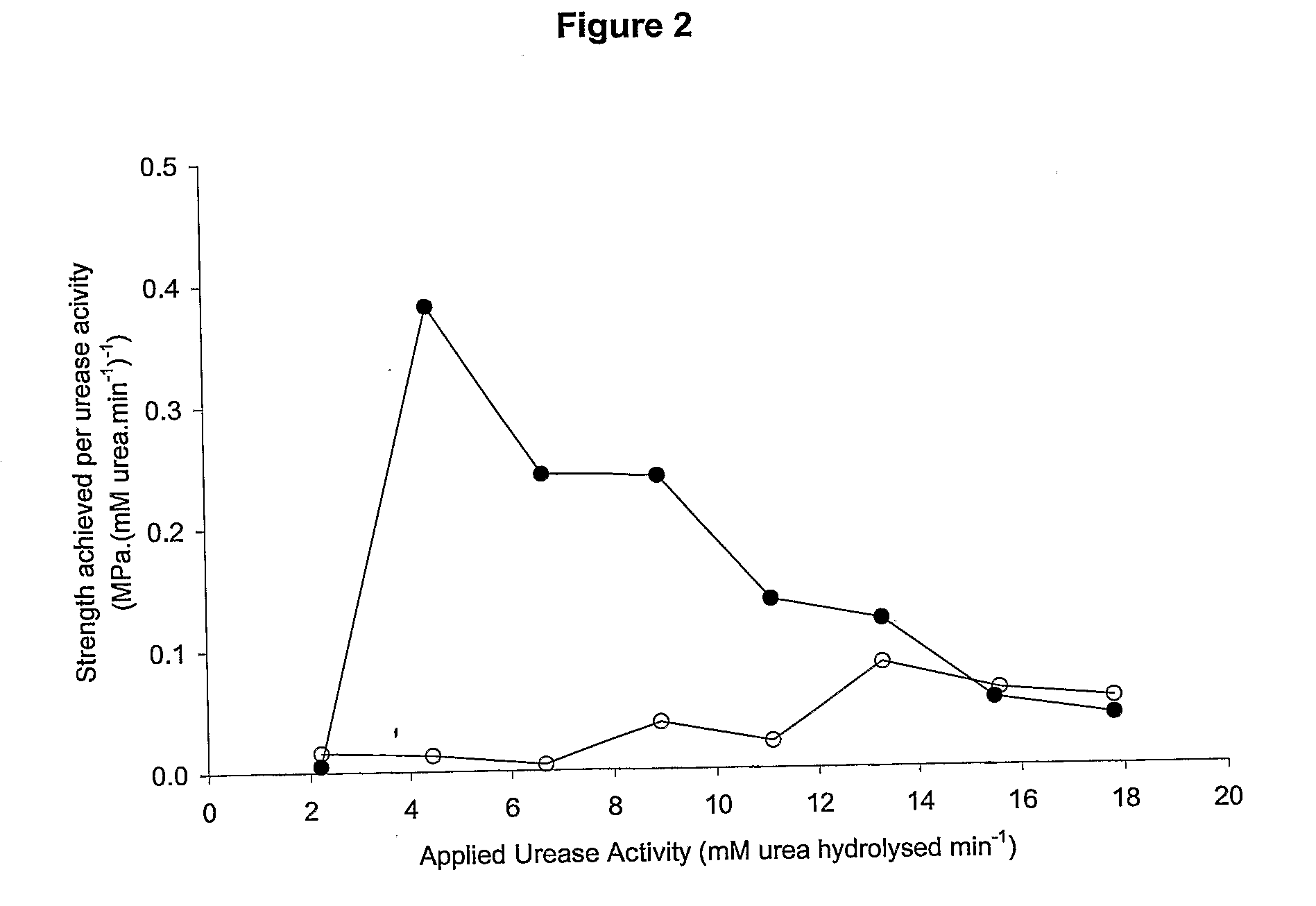
[0180]Bacteria were cultured in the presence of 6 mM Ca2+ and then 650 mL of the bacterial culture (urease activity approximately 10 mM urea hydrolysed / min) was applied to a 1 m sand column by up-flushing under a pressure of 7.5 psi for 11:39 min (1.4 L / hr). The column with the bacterial cells inside was kept at room temperature for a period of 48 hours after which 1.25M Ca2+ and 1.7M urea was up-flushed into the column.

[0181]Results

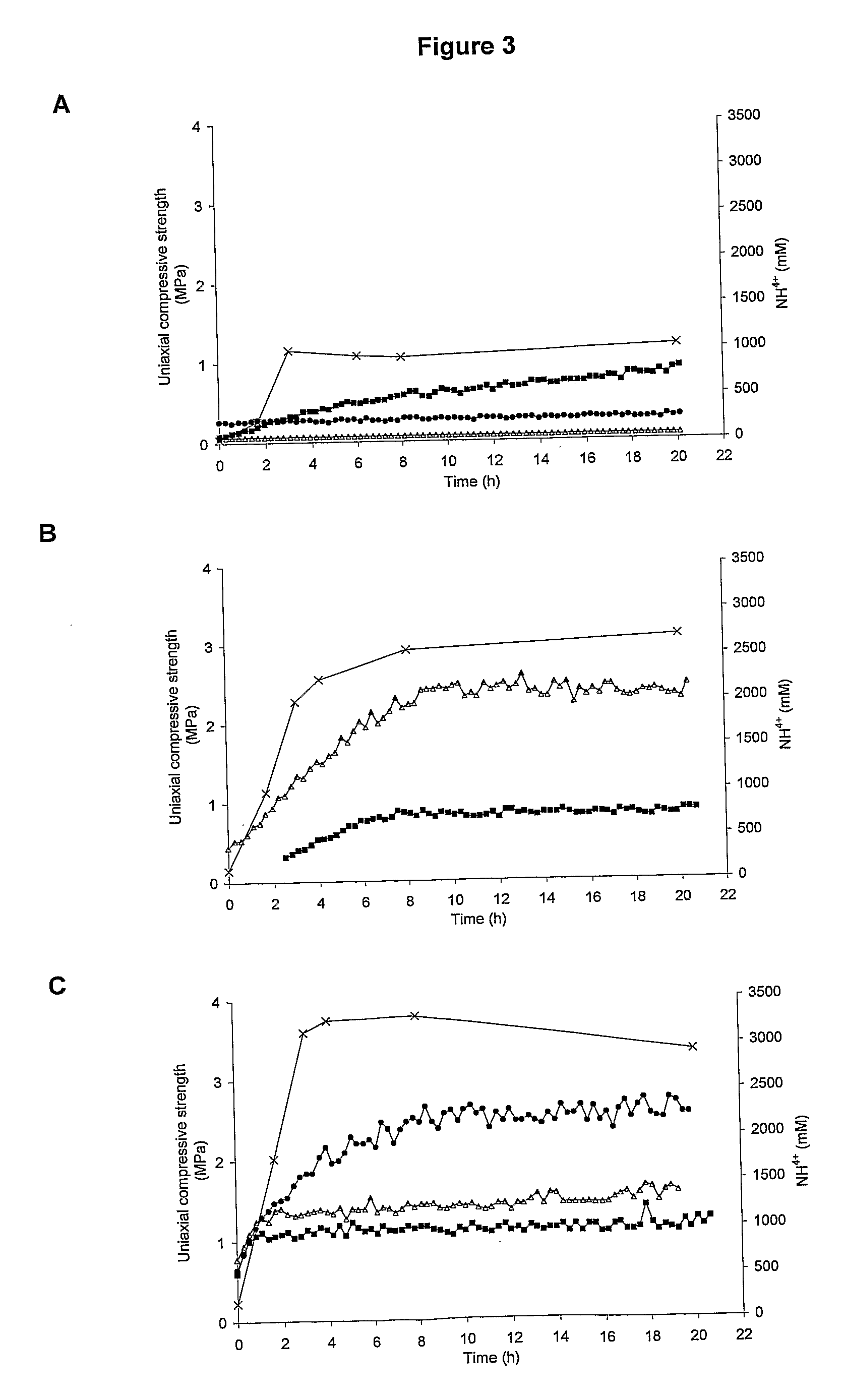
[0182]A uniform strength was obtained. The uniformity of the cemented column was confirmed by ammonium analysis see FIG. 13. Two photographs of the columns after cementation are attached as FIGS. 14A and 14B.


PUM

PropertyMeasurementUnit
Temperatureaaaaaaaaaa
Pressureaaaaaaaaaa
Massaaaaaaaaaa

Abstract

A method of forming a high strength cement in a permeable starting material, the method comprising the step of combining the starting material with effective amounts of (i) a urease producing micro-organism; (ii) urea; and (iii) calcium ions and wherein the effective amount of the urease producing organism provides a urea hydrolysis rate, under standard conditions, of 0.5-50 mM urea hydrolysed.min-1.

Description

FIELD OF THE INVENTION[0001]The present invention relates to a method for forming high strength cement utilising a microbial source of urease such as bacteria that are capable of producing urease. The present invention also relates to various applications of the cement formed by the method.BACKGROUND ART[0002]Urease producing bacteria have been used to remediate the surface and subsurface of permeable media. This process, also known as mineral plugging, has been used in the oil industry where the decreased permeability and porosity of treated media reduces fluid flow and thus can enhance the recovery of oil from reservoirs and / or limit the spread of contaminants from a spill site.[0003]Mineral plugs form as a result of precipitation caused by the increase in pH, which itself is a result of the ammonia formed as a product of the enzymatic breakdown of urea by the urease enzyme. However, whilst these plugs have been used to reduce the porosity / permeability of fissures and other cracks...

Claims


Application Information

Patent Timeline
IPC IPC(8): C04B28/00C12P1/00
CPCC04B24/00C04B28/10C04B2111/00663C04B2111/00732C04B2111/00793C04B2111/72C09K17/00C04B14/10C04B14/28C04B14/361C04B18/167C04B18/26C04B22/085C04B24/121C04B24/126C04B2103/0001Y02W30/91
Inventor KUCHARSKI, EDWARD S.CORD-RUWISCH, RALFWHIFFIN, VICKYAL-THAWADI, SALWA M.
Owner DUST BIOSOLUTIONS GMBH
Why Eureka
Eureka Blog
Learn More