
Saw blade for cutting fiber cement

a technology of fiber cement and saw blades, which is applied in the direction of gear teeth, metal sawing tools, gear teeth, etc., can solve the problems of high cost, slow machining, and inability to “feel” right, so as to improve the quality of cutting in fiber cement workpieces, reduce the amount of chips and dust, and reduce the level of dust

Inactive Publication Date: 2006-10-10
BLACK & DECKER INC
View PDF16 Cites 30 Cited by
  • Summary
  • Abstract
  • Description
  • Claims
  • Application Information

AI Technical Summary

Benefits of technology

[0004]The present invention solves the cost problem and makes the PCD blade capable of cutting a difficult substance like fiber cement. It also makes it possible for the blade to be priced for the consumer, rather than as a high-end specialty product. One way in which the invention is created is to cut the appropriate relieved tooth form out of the PCD / carbon-fused blank or sandwich and then mount the PCD tooth form or tip to the saw blade blank in such a way as to eliminate any further grinding step. Another is to form a relatively large diameter blank of PCD / carbide, and then to form an array of relieved saw blade tips in the blank, such as by EDM cutting, so that, in one embodiment, radially-relieved surfaces of each tip are immediately adjacent the opposite side radially-relieved surface of another tip. Another embodiment of the process of the present invention is to form a PCD / carbide tip in a “square” configuration, such as 0.090 inches by 0.090 inches by 0.125 inches, then connecting the tip to the blade blank, and then grinding the top, radial and tangential relief surfaces in place. Or, it may be desirable to orient the tip on the blade in such a way that the tip needs no grinding to form the desired top relief, and using diamond grinding wheels to grind simultaneously the radial and tangential clearance (relief) surfaces with the tip fixed in place on the blade. Both approaches of the process of the present invention eliminate the conventional need for attaching a pre-formed PCD layer to match the configuration of each carbide tip.
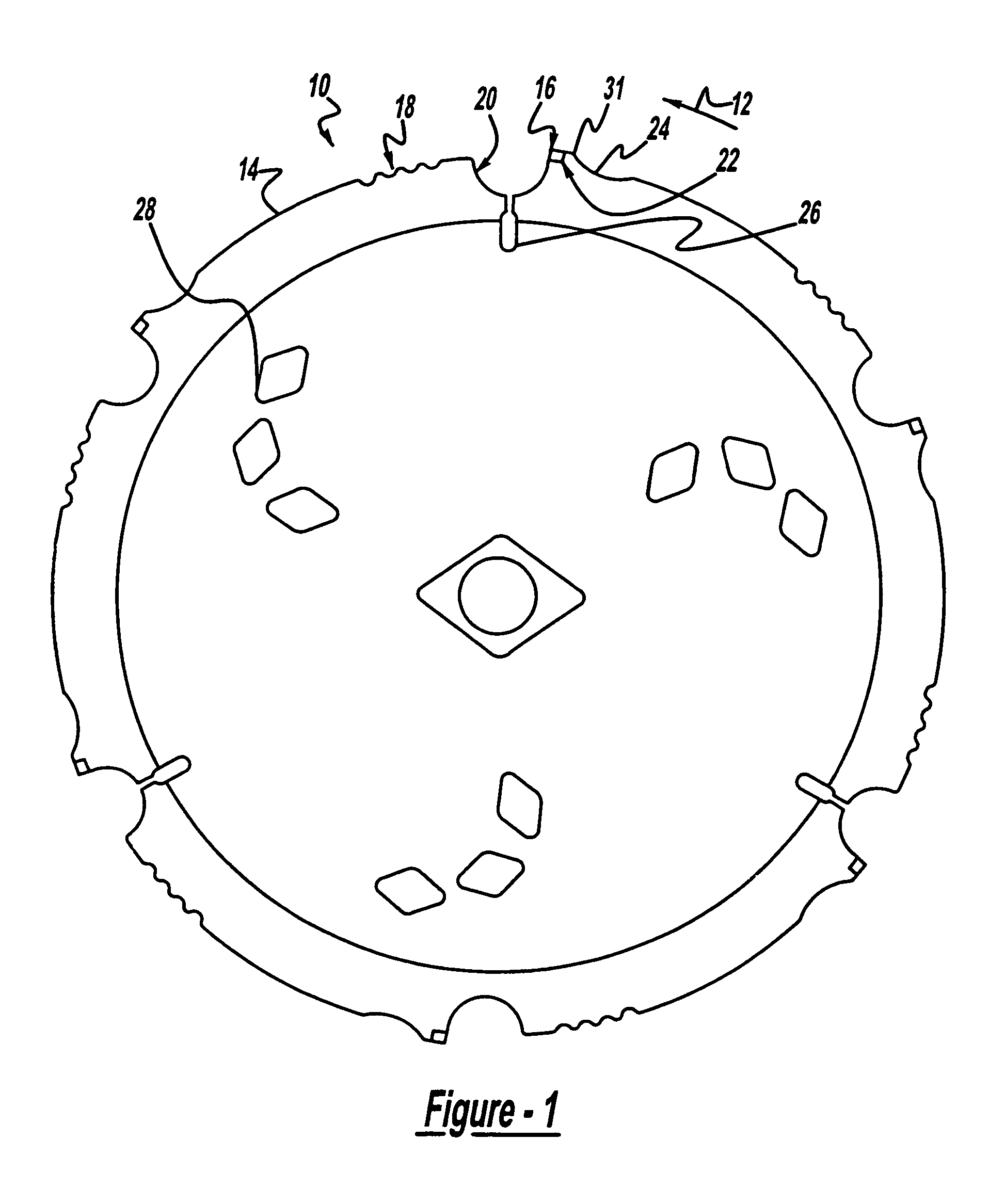
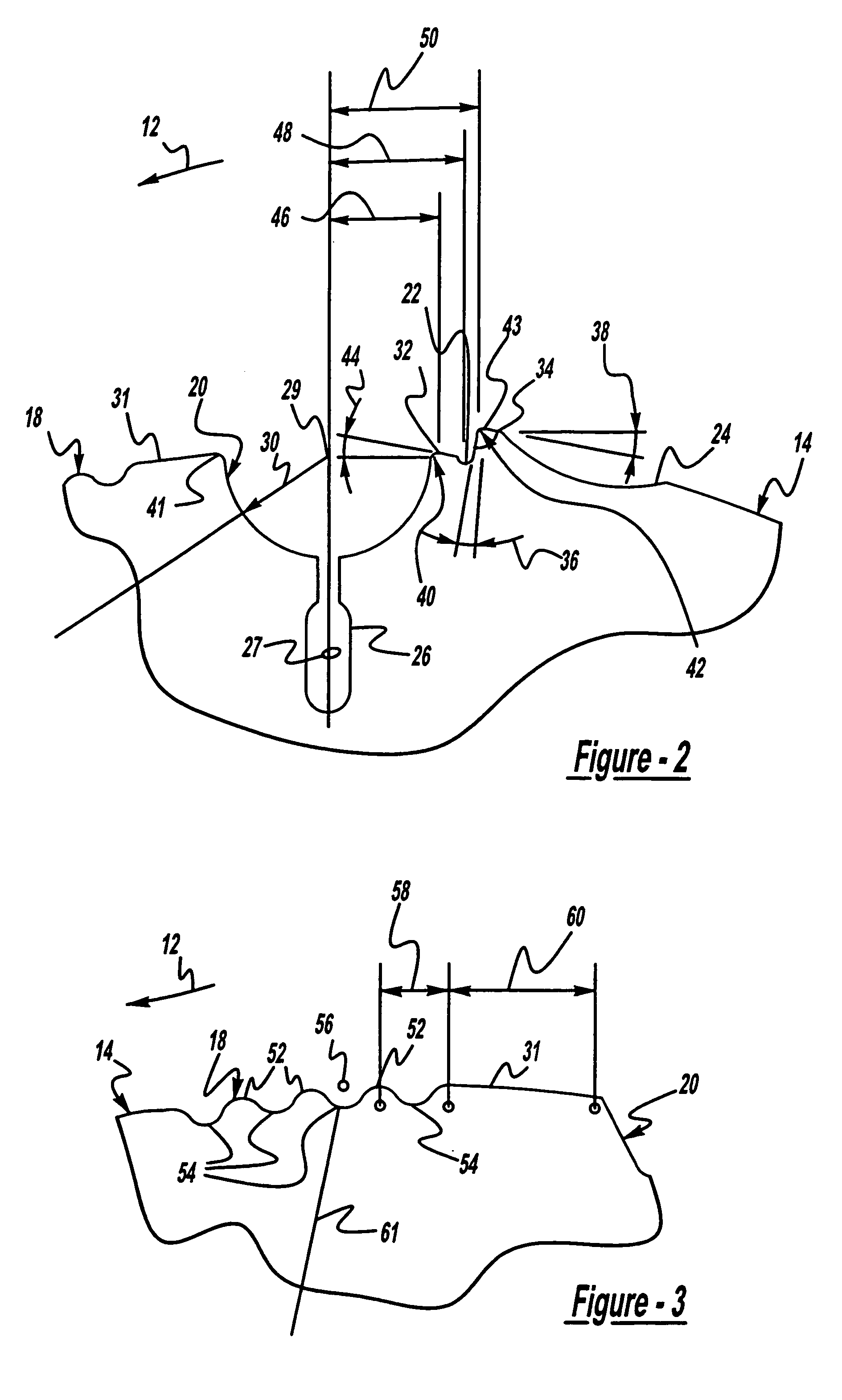
[0006]Recognizing that conventional blades for cutting fiber cement limit the number of teeth to four, because it is believed that fewer teeth generate smaller amounts if fine-particle dust, and further recognizing that four teeth do not satisfactorily clear or minimize the chips and dust packed into the blade—fiber cement interface, the blade of the present invention includes chip and dust minimizers preferably, one in front of each tooth (in the direction of cut of the saw blade). The minimizers of the present invention are created by a sinuous pattern of a plurality of adjacent radially-extending alternating peaks and valleys formed in the rim of the saw blade blank. In a preferred embodiment, each minimizer includes three distinct “hills”, each hill separating two “valleys”, such that the sinuous pattern begins and ends with a valley. The result is a pattern of three hills interspersed among four valleys. Such a minimizer has been found to reduce the amount of chips and dust in the blade-workpiece interface. The minimizers coact with another feature of the blade of the present invention, namely, adjacent, substantially semi-circular, large-diameter gullets at each tip location on the saw blade rim, to further reduce the level of dust.
[0007]Yet a further object of the blade of the present invention is to locate six, not four, sets of PCD tips, gullets and minimizers about the rim of the blade. This has resulted in a significant improvement in the quality of cut in fiber cement workpieces.
[0008]Finally, a further object of the present invention is to orient the PCD / carbide tips of the present invention in their respective locations in the rim of the saw blade so that the tips present a negative hook or rake angle to the workpiece, as opposed to the conventional positive-hook saw blades for cutting fiber cement. The negative-hook orientation of the saw blade tips of the present invention also contributes to the better feel and finish of the blades of the present invention.

Problems solved by technology

Finally, there is a perception by users that conventional blades for cutting fiber cement products, particularly blades with conventional tips formed with polycrystalline diamond joined to tungsten carbide (“PCD”) don't “feel” right.
In view of the wear resistance inherent in the diamond and carbide materials selected, this amount of machining is a slow, expensive process.
This has not proved to be entirely satisfactory.
Further, the conventional design employing four tips doesn't provide a good finish, nor does it provide the user with a good “feel”.

Method used


Image

  • Saw blade for cutting fiber cement
  • Saw blade for cutting fiber cement
  • Saw blade for cutting fiber cement

Examples


Embodiment Construction

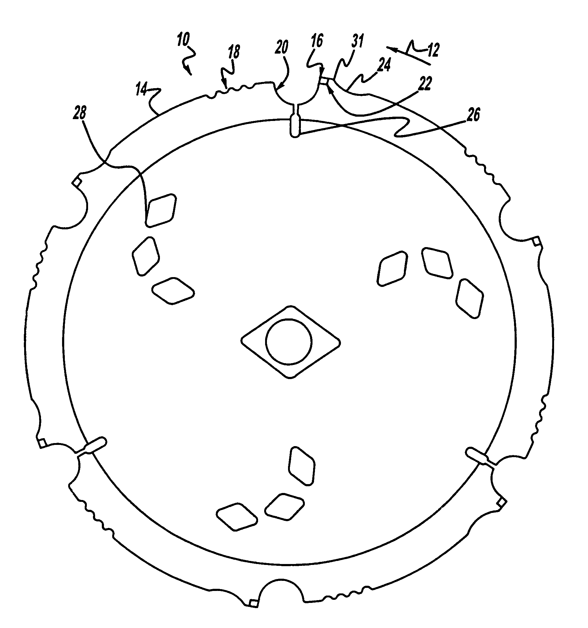
[0027]Referring to FIG. 1, the saw blade of the present invention is referred to generally as 10. The saw blade 10 rotates in the direction shown by arrow 12 when mounted to a saw. The saw blade is formed of a steel plate or blank 14 on which is mounted a plurality of tips 16, where are formed of harder material, such as a fusion of PCD and tungsten carbide (hereinafter referred to as PCD / carbide). The thickness of the steel plate 14 is in the range of from 0.061 inches to 0.065 inches, with the preferred thickness being 0.063 inches. In the preferred embodiment of the circular saw blade 10 of the present invention, the blade itself is cut from sheet or plate steel by a laser process, and then the PCD / carbide tips 16 are brazed to the blade rim 31 in selected locations. Preceding the tip 16 in the direction of rotation 12, is a chip and dust limiter 18, immediately followed by a sweeping (relatively large diameter) gullet 20 for also removing dust. The rim is further formed with a d...


PUM

PropertyMeasurementUnit
radiiaaaaaaaaaa
radiiaaaaaaaaaa
tip hook angleaaaaaaaaaa

Abstract

An improved circular saw blade designed for cutting fiber cement workpieces, which are becoming more and more prevalent on the construction site, includes a PCD / carbide tip (16) mounted in the rim (31) of the saw blade (10) at six, rather than the usual for locations, equally spaced around the blade. The tips are mounted adjacent a relatively large-diameter, semi-circular gullet (20), which itself is preceded by a chip and dust minimizer (18). The minimizer includes several alternating hills (52) and valleys (54) formed in the rim of the saw blade, each hill and valley having the same radius, producing a sinuous array essentially centered on the rim of the blade. It has been discovered that such a dust and chip minimizer reduces the level of dust and chips produced by the blade and clears the same from the kerf generated in the blade-workpiece interface. Ideally, all of the parameters and relief angles for the surfaces on the saw blade tip can be generated by cutting an array of such tips from a large-diameter blank (110) of PCD fused to a layer of tungsten carbide (72), and by mounting the tips onto the blade in such an orientation as to present, preferably, a negative hook or rake angle (74) to the workpiece.

Description

BACKGROUND OF THE INVENTION[0001]Fiber cement products are becoming more and more common on construction sites. As such there has arisen a demand for cutting tools, particularly circular saw blades, that can cut this very difficult material, while reducing the amount of fine dust particles generated. A need also exists for such blades that yield a high quality (straight and smooth) cut in fiber cement workpieces. There has also arisen a need for such blades that are less expensive to produce than conventional diamond blades, but which still exhibit good wear characteristics. Finally, there is a perception by users that conventional blades for cutting fiber cement products, particularly blades with conventional tips formed with polycrystalline diamond joined to tungsten carbide (“PCD”) don't “feel” right.[0002]In the conventional manufacturing process, a PCD tip is attached to the rim of the blade blank at four circumferentially equidistant locations, by brazing the carbide portion t...

Claims


Application Information

Patent Timeline
Patent Type & Authority Patents(United States)
IPC IPC(8): B28D1/04B23F21/03B02C23/18A01K5/01A01K11/00A01K15/02A63H33/18B23D61/02B23D61/04
CPCA01K5/0114A01K15/02A01K15/026A63H33/18B23D61/021B23D61/04B23D65/00B28D1/121
Inventor DASSOULAS, STEPHEN C.CURTSINGER, JOHN R.NOCK, STEFANEDWARDS, DEANLINDBERG, LEGAL REPRESENTATIVE, LAURAMCCLASKEY, STEVELINDBERG, DECEASED, MICHAEL
Owner BLACK & DECKER INC
Learn More