Ultraviolet Irradiation System and Water Quality Monitoring Instrument
- Summary
- Abstract
- Description
- Claims
- Application Information
AI Technical Summary
Benefits of technology
Problems solved by technology
Method used
Image
Examples
first embodiment
[0044]FIG. 5 is a configuration diagram schematically showing a first embodiment of an ultraviolet irradiation system according to the present invention.
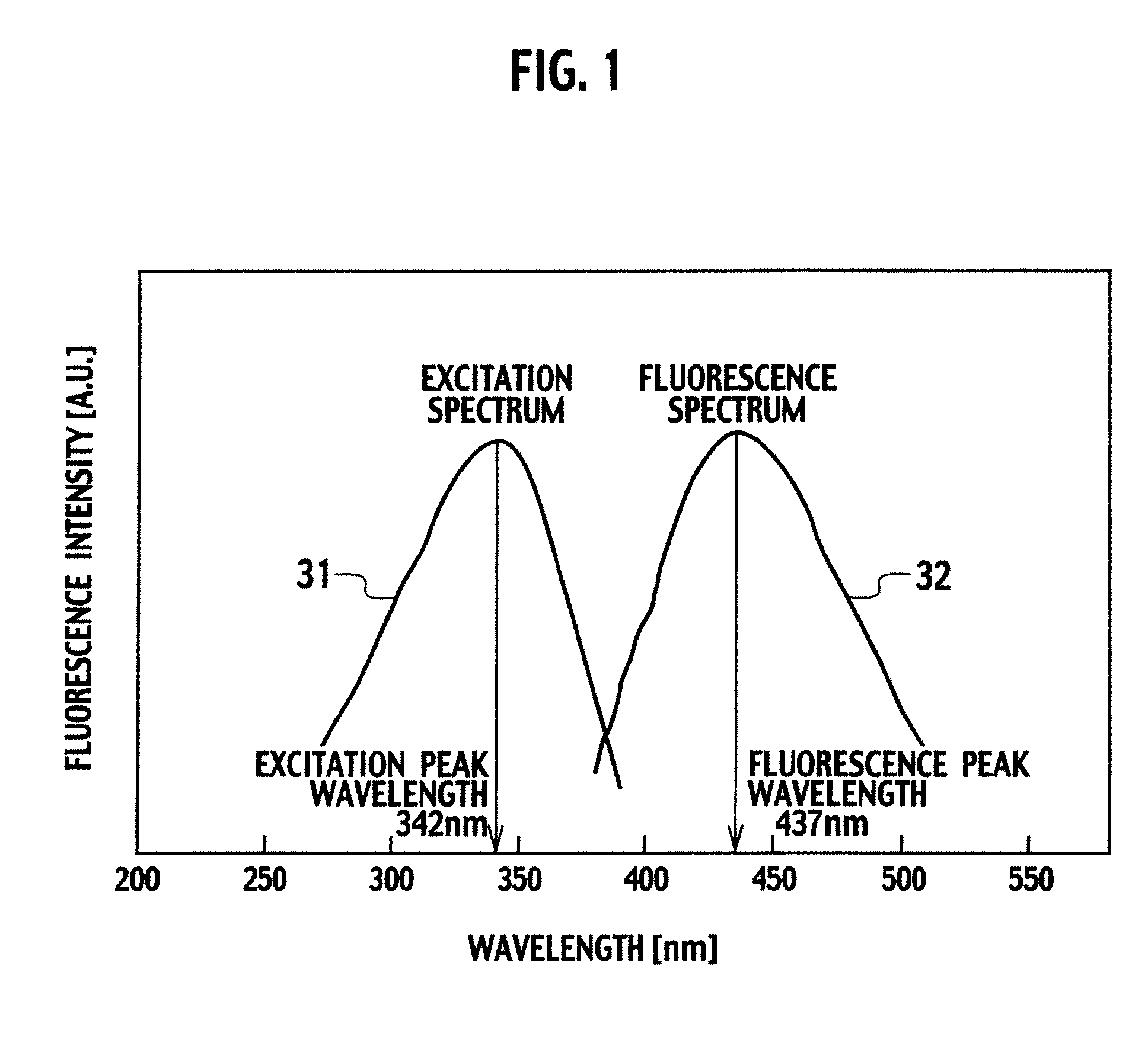
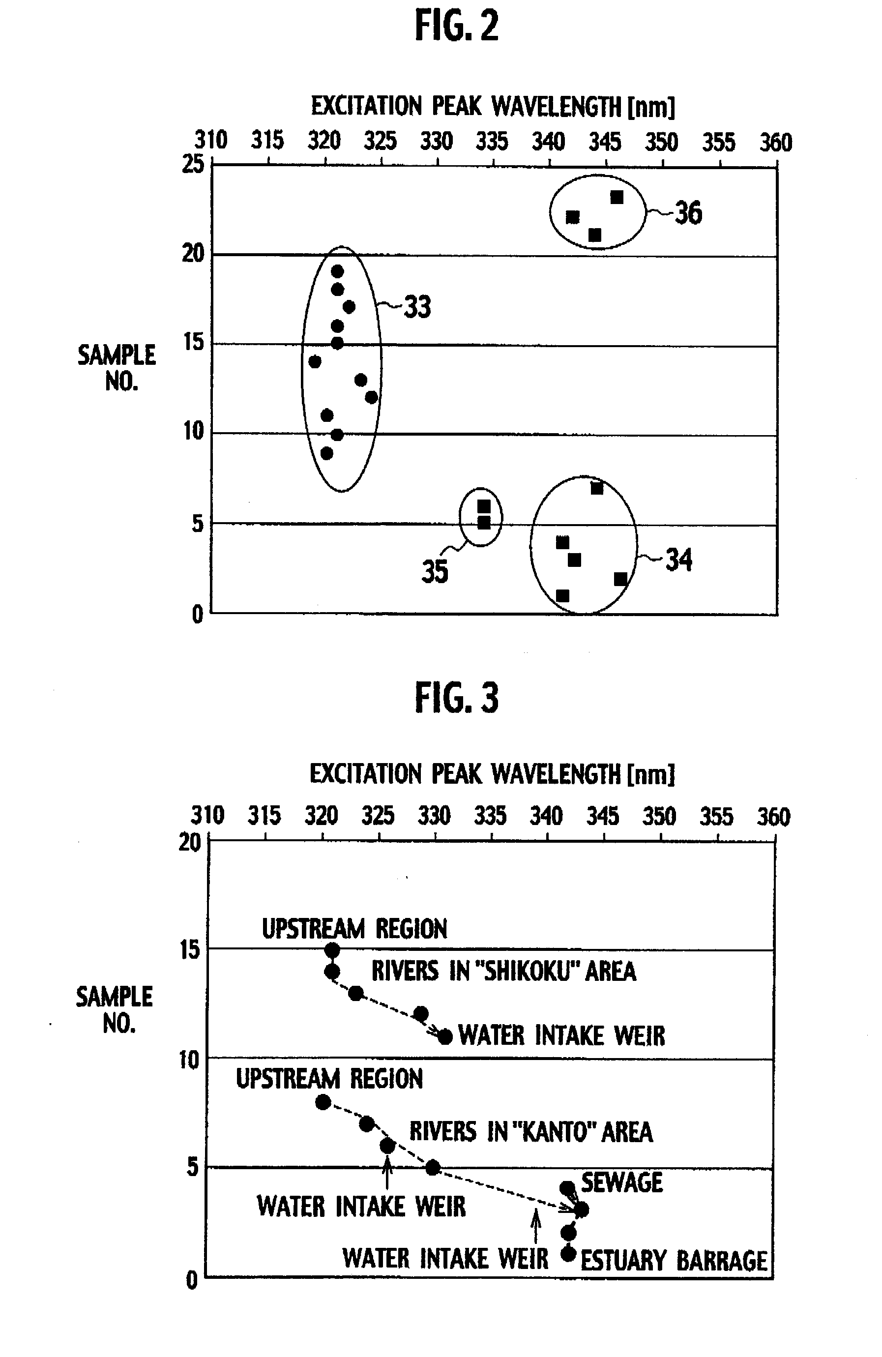
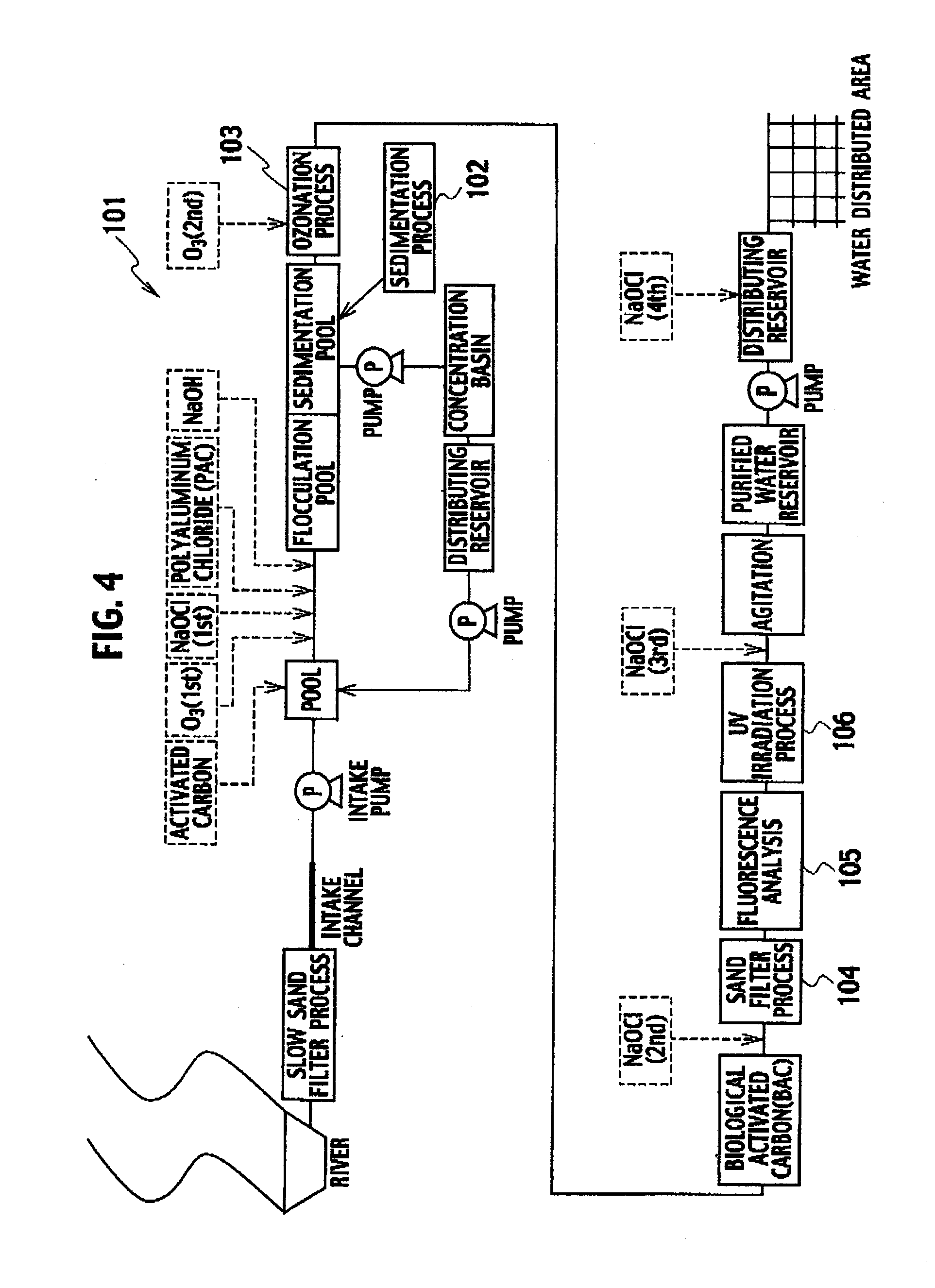
[0045]As shown in FIG. 5, an ultraviolet irradiation system 1a includes an ultraviolet irradiation tank 2, an ultraviolet irradiation device 3, a fluorometer 6, an ultraviolet (UV) irradiation level control device 7 and an ultraviolet (UV) power supply 8. The ultraviolet irradiation tank 2 continuously takes in pre-treated water 4. Here, the pre-treated water 4 refers to water in a state after water purification, such as a sand filtration process and a high treatment process, has been performed on river raw water taken in and before a third injection of chloride is carried out (see FIG. 4). The ultraviolet irradiation device 3 is provided in the ultraviolet irradiation tank 2, generates ultraviolet rays having an intensity corresponding to a driving voltage supplied from the ultraviolet power supply 8 (to be described later) and irr...
second embodiment
[0056]Next, a description will be given of a second embodiment of the ultraviolet irradiation system according to the present invention. Note that, since a system configuration is the same as that of the first embodiment shown in FIG. 5, a description will be given by using FIG. 5 without modification.
[0057]The ultraviolet irradiation level control device 7 in the first embodiment sets the excitation peak wavelength and the ultraviolet irradiation level target value so as to have a linearly proportional relationship. In other words, the ultraviolet irradiation level target value in the first embodiment is a linear function of the excitation peak wavelength. Meanwhile, an ultraviolet irradiation level control device 7 in the second embodiment sets an ultraviolet irradiation level target value to be a step function of an excitation peak wavelength. Specifically, hygienic reliability and energy saving are further improved by setting the ultraviolet irradiation level target value to be ...
third embodiment
[0062]FIG. 9 is a configuration diagram schematically showing a third embodiment of the ultraviolet irradiation system according to the present invention. Note that parts corresponding to the parts shown in FIG. 5 are denoted by the same reference numerals in FIG. 9.
[0063]As shown in FIG. 9, an ultraviolet irradiation system 1b in the third embodiment is different from the ultraviolet irradiation system 1a in the first and second embodiments shown in FIG. 5 in the following points. Specifically, 1) a fluorometer 10 fixes a fluorescence wavelength to 425 nm, scans an excitation wavelength to obtain an excitation spectrum of pre-treated water 4 and continuously measure both a fluorescence intensity and an excitation peak wavelength. Moreover, 2) there is provided an ultraviolet irradiation level control device 12 which shifts an ultraviolet irradiation level target value in stages according to the excitation peak wavelength and a correction coefficient. Further, 3) there is provided a...
PUM
 Abstract
Description
Claims
Application Information
 - R&D
- Intellectual Property
- Life Sciences
- Materials
- Tech Scout
- Unparalleled Data Quality
- Higher Quality Content
- 60% Fewer Hallucinations
Browse by: Latest US Patents, China's latest patents, Technical Efficacy Thesaurus, Application Domain, Technology Topic, Popular Technical Reports.
© 2025 PatSnap. All rights reserved.Legal|Privacy policy|Modern Slavery Act Transparency Statement|Sitemap|About US| Contact US: help@patsnap.com


