Noncircular transient fluid fuel injector control channels in propellant injector combustion systems

a control channel and propellant injection technology, applied in the direction of gas turbine plants, hot gas positive displacement engine plants, intermittent jet plants, etc., can solve the problems of affecting and contaminating spacecraft surfaces. , to achieve the effect of improving the efficiency of bipropellant combustion systems

Inactive Publication Date: 2008-10-02
THE AEROSPACE CORPORATION
View PDF6 Cites 6 Cited by
  • Summary
  • Abstract
  • Description
  • Claims
  • Application Information

AI Technical Summary

Benefits of technology

[0012]An object of the invention is to improve the efficiency of bipropellant combustion systems.
[0016]The invention is directed to modifying the cross-sectional area of propellant injectors. The injector orifices are shaped to insure that the design mixture ratio, which is achieved in steady state operation, is also achieved in the shortest burn times. At least one of the injectors is noncircular or the number of fuel and oxidizer channels is unequal to achieve synchronized flow response. Alternatively, the injectors can be shaped to implement a hotter mixture ratio for short burn times that will achieve design thrust levels more quickly, while still delivering the design mixture ratio for longer burns. The synchronization of propellant response times also allows the reduced flow in short pulse operation of the bipropellant thruster to be used to throttle the thruster over a wide range without damaging the engine or contaminating the spacecraft with the products of incomplete combustion. These and other advantages will become more apparent from the following detailed description of the preferred embodiment.

Problems solved by technology

Propellant consumption in limit cycle operations is particularly sensitive to the minimum impulse bit.
Incomplete combustion of pulsed bipropellant thrusters and can lead to condensed phase reaction intermediates that can contaminate spacecraft surfaces, and even cause erosion.
In some cases, the reaction intermediates formed in incomplete combustion can lead to hard-starts, or engine damage.
For a short pulse meant to deliver the minimum impulse bit, however, the combustion chamber may never reach steady state conditions within the pulse.
Incomplete combustion could be one of the factors contributing to the low efficiency and high variability of pulsed thrusters, as well as the generation of contaminants.
For missions where the required total impulse is less than 45,000 N-s monopropellant systems are used because the propellant savings does not justify the increased complexity.
The few millisecond oxidizer lead provided by a smaller oxidizer dribble volume in the current designs is not enough to compensate for this mismatch.
The fuel rich mixture results in lower combustion temperatures, and incomplete combustion, which causes several problems.
Incomplete combustion can lead to the accumulation of combustion intermediates.
The fuel oxidizer reaction products produce undesirable high-energy condensation.
The products have been linked to several problems with thrusters, such as hard starts, and even damage to the thruster body.
The fuel oxidizer reaction products can also contaminate other spacecraft surfaces where there is a lower vapor pressure than fuel, oxidizer, or combustion products.
Unequal propellant response times can also lead to combustion instability.
Prior propellant injector systems have used conventional dribble channels and injectors producing mismatches in fuel and oxidizer delivery, contamination, and spikes in the combustion performance.

Method used


Image

  • Noncircular transient fluid fuel injector control channels in propellant injector combustion systems
  • Noncircular transient fluid fuel injector control channels in propellant injector combustion systems

Examples


Embodiment Construction

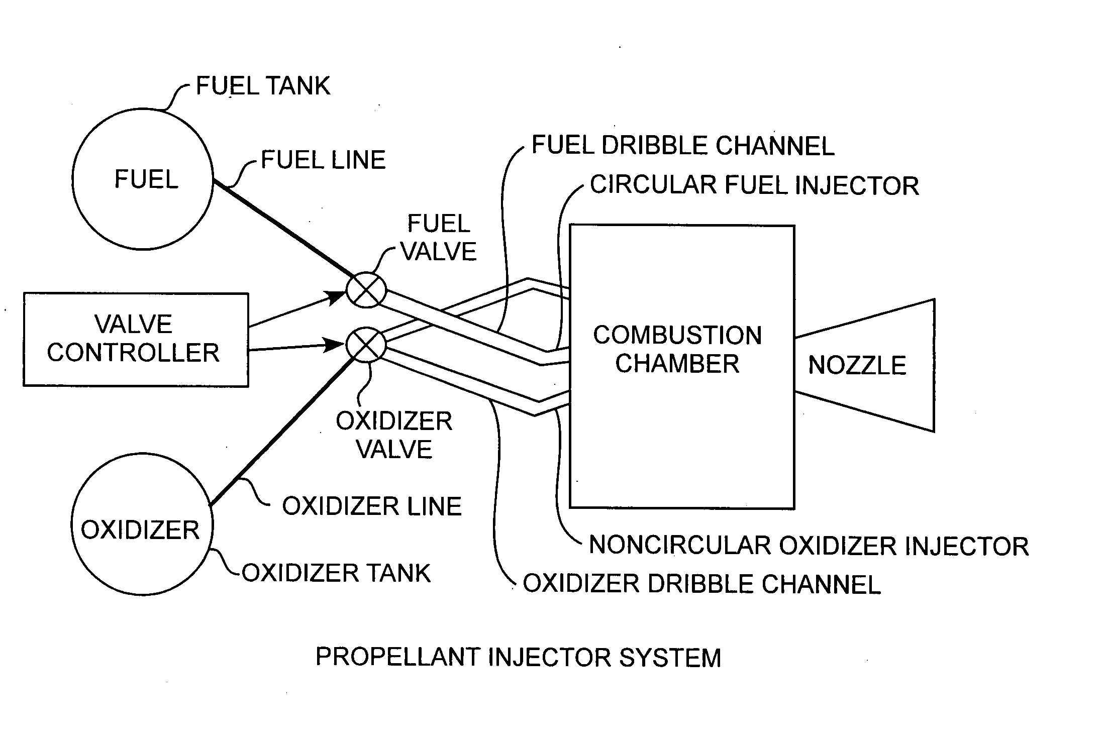
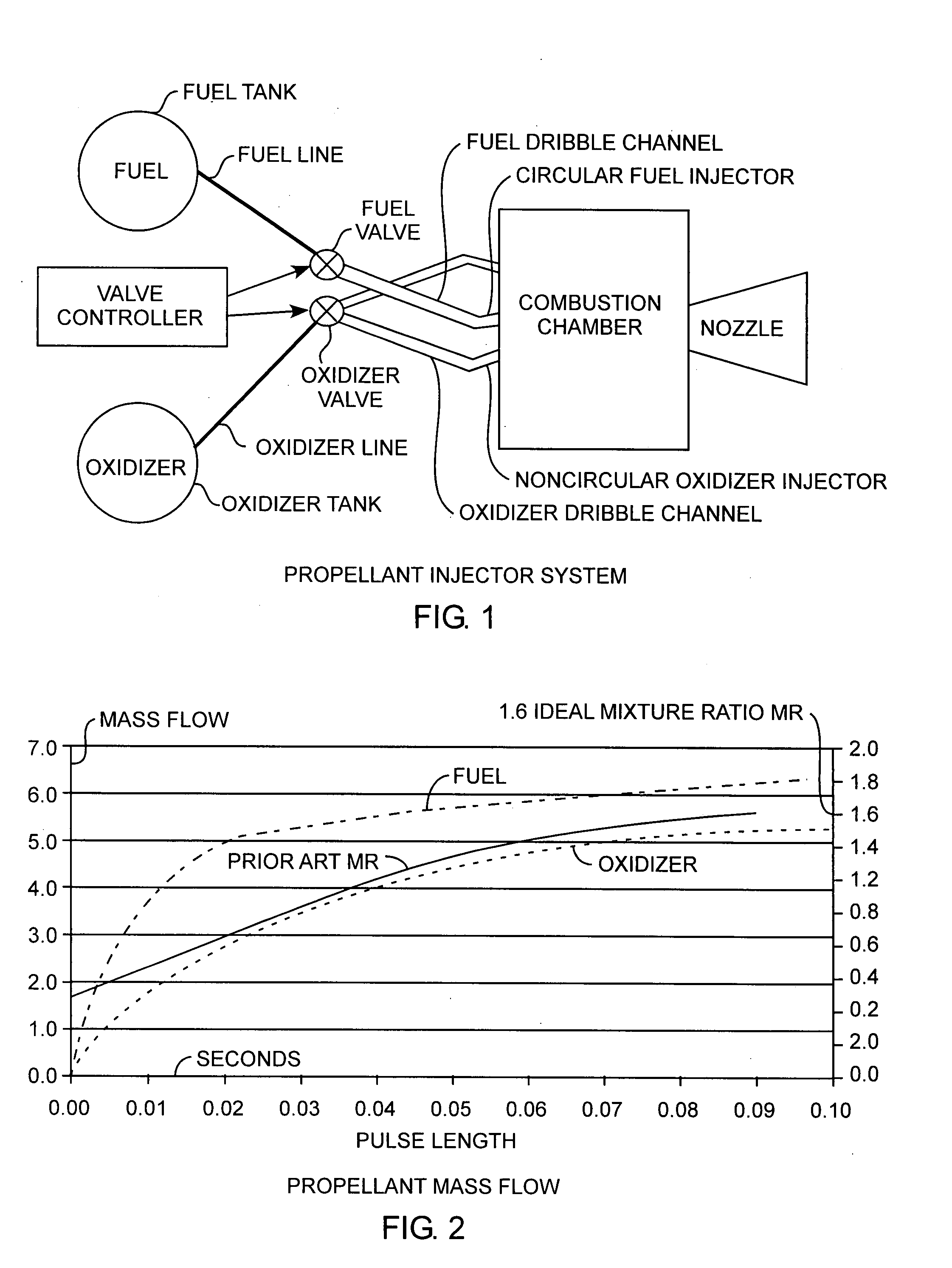
[0019]An embodiment of the invention is described with reference to the figures using reference designations as shown in the figures. Referring to FIG. 1, a fuel tank is used to store and contain liquid fuel and pressurant gas. A fuel line extends from the fuel tank to a fuel valve for controlling fuel flow from the fuel line into a fuel dribble channel. The dribble channel, in the preferred form, is a circular fuel channel connected between the fuel valve and a combustion chamber. The fuel passes from the tank to combustion chamber as limited by the fuel valve, the fuel dribble channel, and fuel injector. In the preferred form, the fuel injector is circular fuel injector orifice. A valve controller controls the fuel valve to control the flow of fuel from the fuel tank to the combustion chamber under system controls. The injector orifice, that is the circular fuel injector, is the last portion of the fuel line extending between the fuel valve and the combustion chamber. The last por...


PUM


Abstract

A fuel injector system for combustion engines and motors, such as pulsed bipropellant thrusters, includes noncircular fuel and oxidizer injectors at the ends of respective dribble channels for controlling the mixture ratio of the propellants passing into a combustion chambers for maintaining a desire or ideal mixture ratio as determined by the cross-sectional area of the injectors well suited for pulse combustion fuel injector systems.

Description

FIELD OF THE INVENTION[0001]The invention relates to the field of combustion engines and motors. More particularly, the present invention relates to sizing of fuel and oxidizer dribble channels for improved propellant injection and combustion.BACKGROUND OF THE INVENTION[0002]In-space propulsion is an important part of most space missions, accounting for an average of 40% of the launched mass of unmanned systems. Pulsed bipropellant thrusters are commonly used on spacecraft for in-space propulsion. Short-pulse operation is particularly useful for attitude control, the figure of merit being the minimum impulse bit. Propellant consumption in limit cycle operations is particularly sensitive to the minimum impulse bit. A rough estimate of the size of the minimum impulse bit of a thruster is the steady state force generated times the pulse width, but significant deviations from this concept are found experimentally. Pulse widths as short as 0.01 s are used operationally. The efficiency of...

Claims


Application Information

Patent Timeline
IPC IPC(8): F02K9/28
CPCF02K7/02F02K9/42F02K9/52F02K9/58
Inventor BRADY, BRIAN BLAISE
Owner THE AEROSPACE CORPORATION
Why Eureka
Try Eureka