
Flat panel display

Inactive Publication Date: 2008-09-25
SAMSUNG SDI CO LTD
View PDF5 Cites 11 Cited by
  • Summary
  • Abstract
  • Description
  • Claims
  • Application Information

AI Technical Summary

Benefits of technology

[0009]Aspects of the present invention have been made to provide a flat panel display that supplies a predetermined voltage to each electrode through a lead line, and / or other advantages.

Problems solved by technology

Therefore, voltage values supplied to the respective electrodes may not be maintained at a predetermined level.
In addition, since a voltage of a predetermined level may not be uniformly supplied to electron emission units corresponding to the respective electrodes, the amount of electrons emitted from the respective electron emission units varies.
Therefore, luminance of the display device may not be uniform for each pixel.

Method used


Image

  • Flat panel display
  • Flat panel display
  • Flat panel display

Examples


Embodiment Construction

[0030]Reference will now be made in detail to the aspects of the present invention, examples of which are illustrated in the accompanying drawings, wherein like reference numerals refer to the like elements throughout. The aspects are described below in order to explain the present invention by referring to the figures.

[0031]In the figures, the dimensions of layers and regions may be exaggerated for clarity. It will also be understood that when a layer or element is referred to as being “on” or “over” another layer or substrate, it can be directly on the other layer or substrate, or intervening layers may also be present. Further, it will be understood that when a layer is referred to as being “under” or “below” another layer, it can be directly under, or one or more intervening layers may also be present.

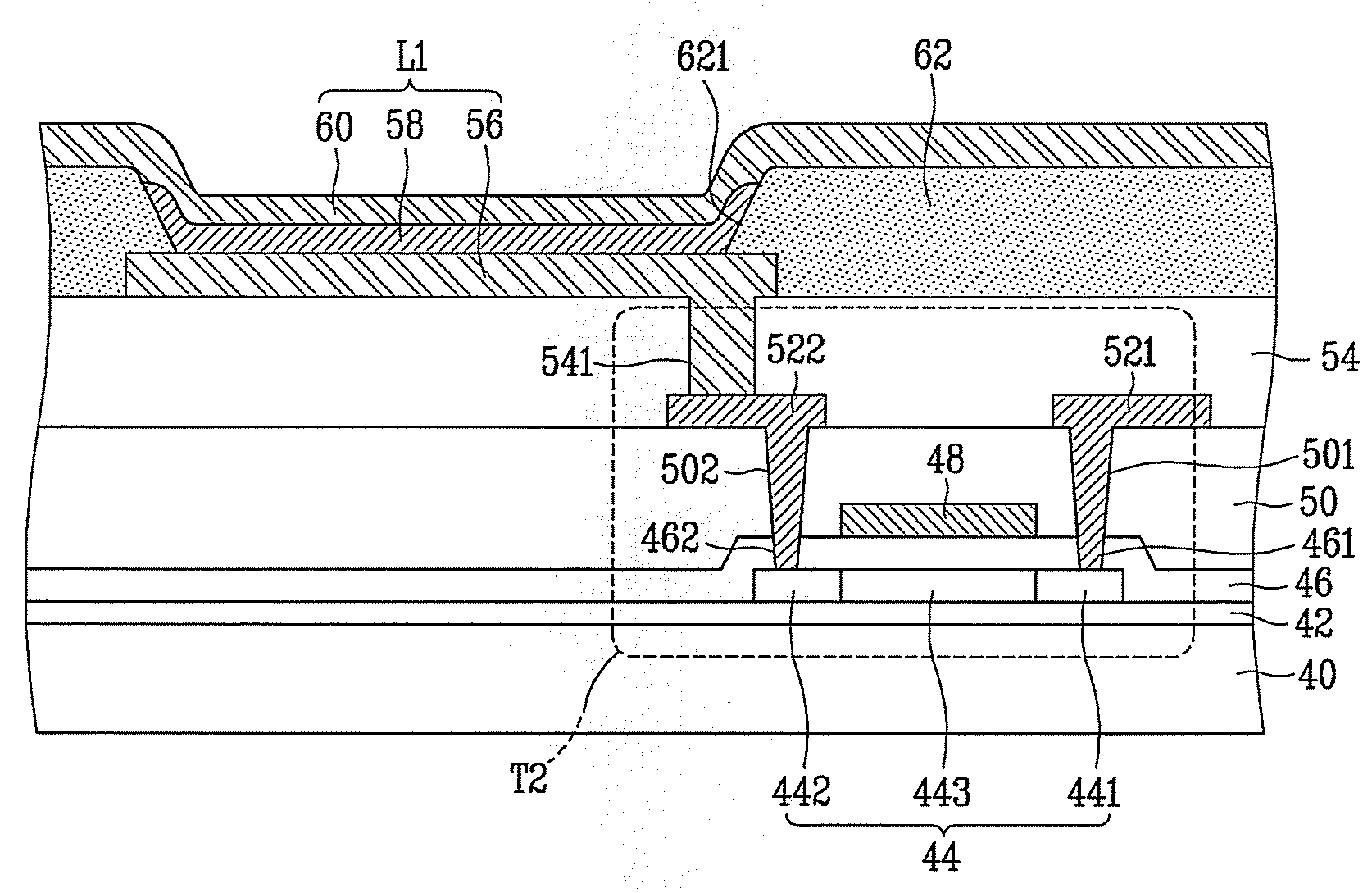
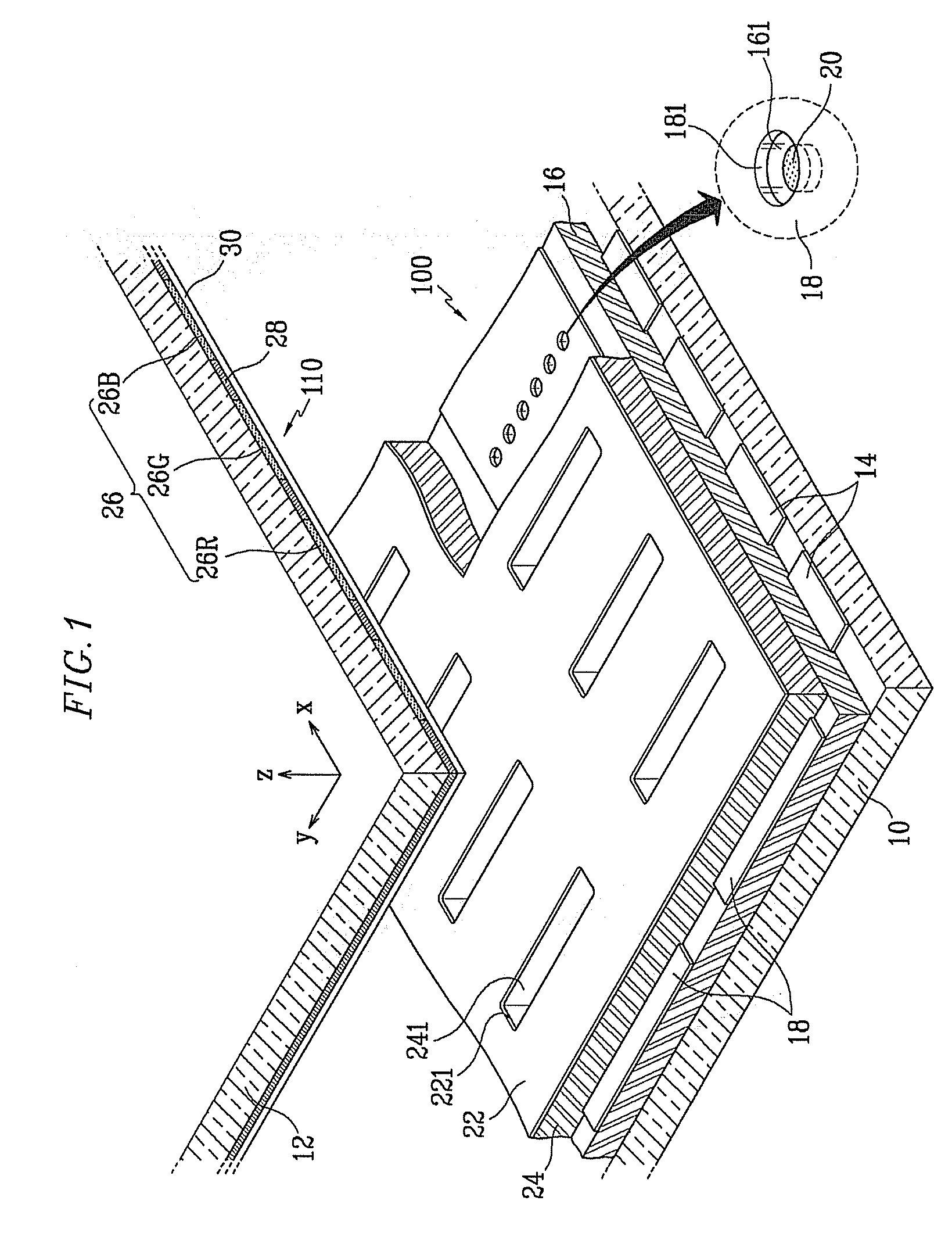
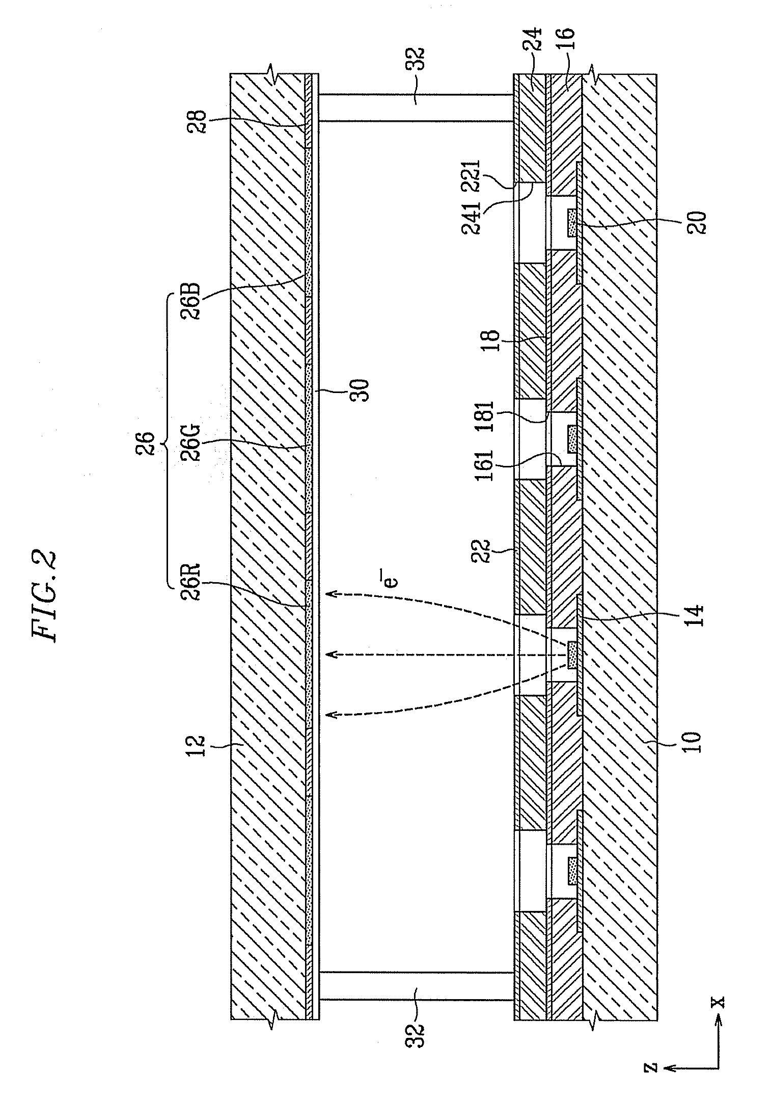
[0032]FIG. 1 is a partial exploded perspective view of a flat panel display according to an aspect of the present invention. FIG. 2 is a cross-sectional view of the flat panel disp...


PUM


Abstract

A flat panel display to maintain resistance of lines at the same level to reduce a luminance difference between the lines includes a plurality of electrodes and a plurality of lead lines to respectively connect a plurality of pads to the plurality of electrodes. The lead lines are formed in a parallelogram shape in which resistivity and line width are the same for each, and a length L and a line width W of each lead line are selected such that a value obtained by dividing the length L by the line width W may satisfy an equation ofL1W1=L2W2=L3W3=…=LnWn,where L1, L2, L3, . . . , and Ln respectively refers to long side lengths, which are direct line distances between the electrode and the pad, of the respective lead lines formed in the parallelogram shape, and W1, W2, W3, . . . , and Wn respectively refers to widths, which are short side vertical distances of the respective lead lines formed in the parallelogram shape.

Description

CROSS-REFERENCE TO RELATED APPLICATION[0001]This application claims the benefit of Korean Application No. 2007-28094 filed Mar. 22, 2007, in the Korean Intellectual Property Office, the disclosure of which is incorporated herein by reference.BACKGROUND OF THE INVENTION[0002]1. Field of the Invention[0003]Aspects of the present invention relate to a flat panel display. More particularly, aspects of the present invention relate to an electrode pattern of a flat panel display.[0004]2. Description of the Related Art[0005]Generally, a flat panel display (FPD) includes front and rear substrates that are combined to form a closed and sealed container having a predetermined inner space. A structure to emit light of a predetermined color from each pixel is provided in the sealed container so as to realize or display an image.[0006]There are various types of flat panel displays, including a liquid crystal display (LCD), a plasma display panel (PDP), a vacuum fluorescent display, an electron e...

Claims


Application Information

Patent Timeline
IPC IPC(8): H01J1/62
CPCG02F1/1345H01J29/92H01J31/127H01J2329/92H05K2201/09727H05K1/117H05K2201/0784H05K2201/09236H01L27/3276H10K59/131H01J1/30H05B33/26H01J29/02
Inventor LEE, BYONG-GON
Owner SAMSUNG SDI CO LTD
Learn More