
Support Member Assembly for Conductive Contact Members

a technology of support member and contact member, which is applied in the direction of measurement lead/probe, semiconductor/solid-state device testing/measurement, instruments, etc., can solve the problems of time-consuming process for machining silicon members, difficult to machine ceramics, and difficult to meet the requirements of silicon. , to achieve the effect of economic and simple arrangemen

Inactive Publication Date: 2008-09-18
NHK SPRING CO LTD
View PDF9 Cites 4 Cited by
  • Summary
  • Abstract
  • Description
  • Claims
  • Application Information

AI Technical Summary

Benefits of technology

The present invention provides a support member assembly for supporting conductive contact members in a contact probe head or the like. The assembly allows for the formation of small holder holes at high precision and in high density. The support member is made of a reinforcing member integrated with the support member, which ensures overall mechanical strength of the assembly. The reinforcing member can be made of metallic materials, glass, ceramics, or silicon, and can be inserted molded or externally attached to the support member. The reinforcing member can be used to reinforce the support member and ensure positional accuracy of the conductive contact members. The support member assembly is economical and easy to manufacture.

Problems solved by technology

However, machining a silicon member is a time-consuming process, and silicon requires electric insulation.
Ceramics are known to be difficult to machine.
Glass involves significant dimensional errors when machining, and this results in a poor yield factor.
A low thermal expansion alloy is difficult to machine, and requires electric insulation.
Therefore, when such materials are selected for the support member of a contact probe head, the production efficiency is low, and the production cost is high.
However, in a contact probe head having a large number of conductive contact members arranged in a support member at a high density, the pressure produced from such a large number of conductive contact members may cause a warping of the support member.
The thermal expansion may cause positional errors of the conductive contact members (conductive needle members), and the access point of each conductive contact member may unacceptably offset from the desired point.

Method used


Image

  • Support Member Assembly for Conductive Contact Members
  • Support Member Assembly for Conductive Contact Members
  • Support Member Assembly for Conductive Contact Members

Examples


Embodiment Construction

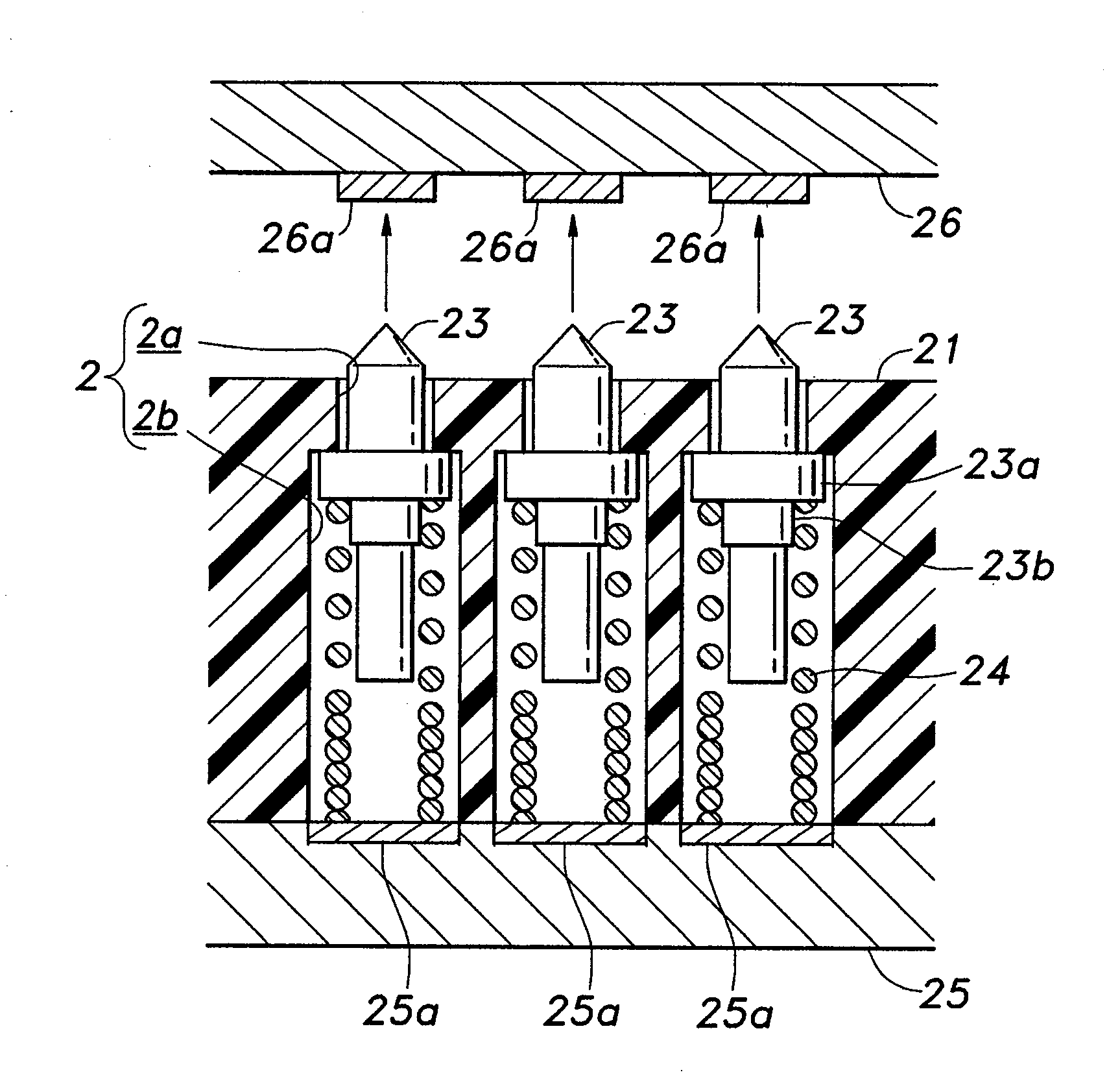
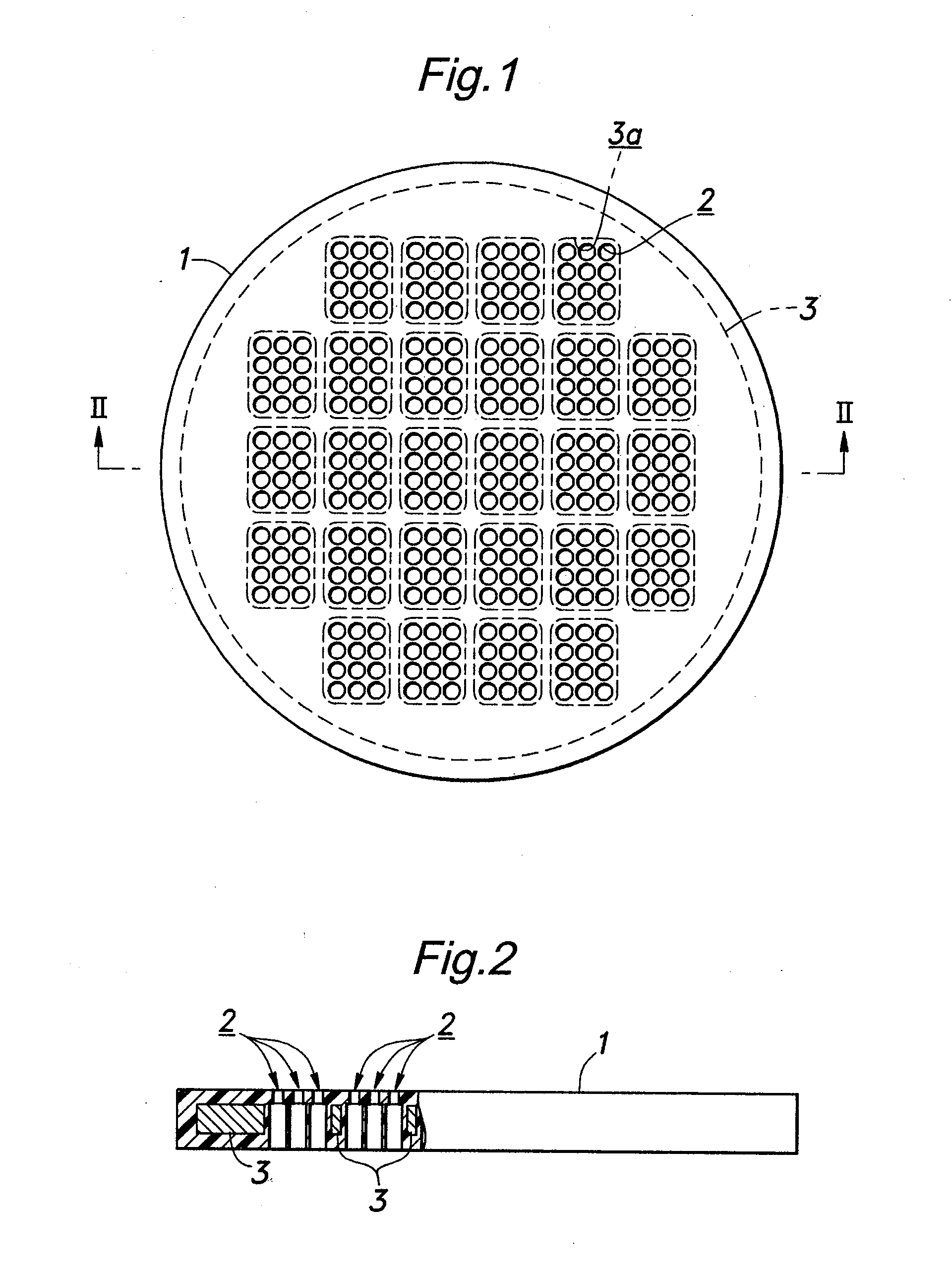
[0034]FIG. 1 is a plan view of a support member assembly 1 for supporting conductive contact members in a contact probe head embodying the present invention, and FIG. 2 is a sectional view taken along line II-II of FIG. 1. The conductive contact members in the form of needle members and coil springs which are to be combined with the support member assembly 1 are omitted in these drawings as they are conventional by themselves. The present invention is applicable also to cases where the coil springs additionally serve as conductive contact members.

[0035]When the object to be tested consists of an 8-inch wafer, the support member assembly 1 may consist of a disk having a diameter of approximately 8 inches (approximately 200 mm) as shown in the drawings. The thickness of the support member assembly 1 is typically in the order of 0.5 to 1.5 mm, but may also be in the order of 0.1 to 0.2 mm when a laminated structure is employed. An 8-inch wafer typically contains from tens to hundreds o...


PUM


Abstract

Provided is a support member assembly suitable for use in a contact probe head comprising a support member formed with a plurality of holder holes for supporting conductive contact members in a mutually parallel relationship, and a reinforcing member integrally formed with the support member and extending in a part of the support member devoid of any holder holes. The reinforcing member increases the overall mechanical strength of the support member assembly, and prevents the thermal deformation of the support member. Because the holder holes are formed in the support member made of material suitable for forming holes, such as plastic material and ceramic material, the holder holes can be formed at high precision and at low cost.

Description

CROSS REFERENCE TO RELATED APPLICATIONS[0001]The present application is a divisional of U.S. patent application Ser. No. 11 / 125,290, filed on May 9, 2005, which is a continuation-in-part of now-abandoned U.S. patent application Ser. No. 10 / 481,089, filed on Jul. 6, 2004 by Toshio Kazama, entitled “Support Member Assembly for Conductive Contact Members,” which is in turn the National Stage of International Application No. PCT / JP01 / 05554, filed Jun. 28, 2001, all of which are incorporated herein by reference in their entireties.TECHNICAL FIELD[0002]The present invention generally relates to a support arrangement for conductive contact members for contact probe heads, electric sockets and other applications, and in particular relates to a support member assembly for conductive contact members for contact probe heads suitable for burn-in tests of semiconductor related components.BACKGROUND OF THE INVENTION[0003]In recent years, burn-in tests are routinely conducted as a part of a test p...

Claims


Application Information

Patent Timeline
Patent Type & Authority Applications(United States)
IPC IPC(8): G01R31/02G01R1/06G01R1/04G01R1/073G01R31/28H01L21/66
CPCG01R1/07314G01R31/2889G01R1/07371
Inventor KAZAMA, TOSHIO
Owner NHK SPRING CO LTD
Learn More