Extreme ultra violet light source apparatus
a technology of ultra violet light source and filter, which is applied in the field oflpp, can solve the problems of easy deterioration and/or breakage of spf b>114/b>, thin spf b>114/b>, etc., and achieve the effect of preventing deterioration and/or breakage of the filter
- Summary
- Abstract
- Description
- Claims
- Application Information
AI Technical Summary
Benefits of technology
Problems solved by technology
Method used
Image

Examples
first embodiment
[0049]Next, an EUV light source apparatus according to the present invention will be explained.
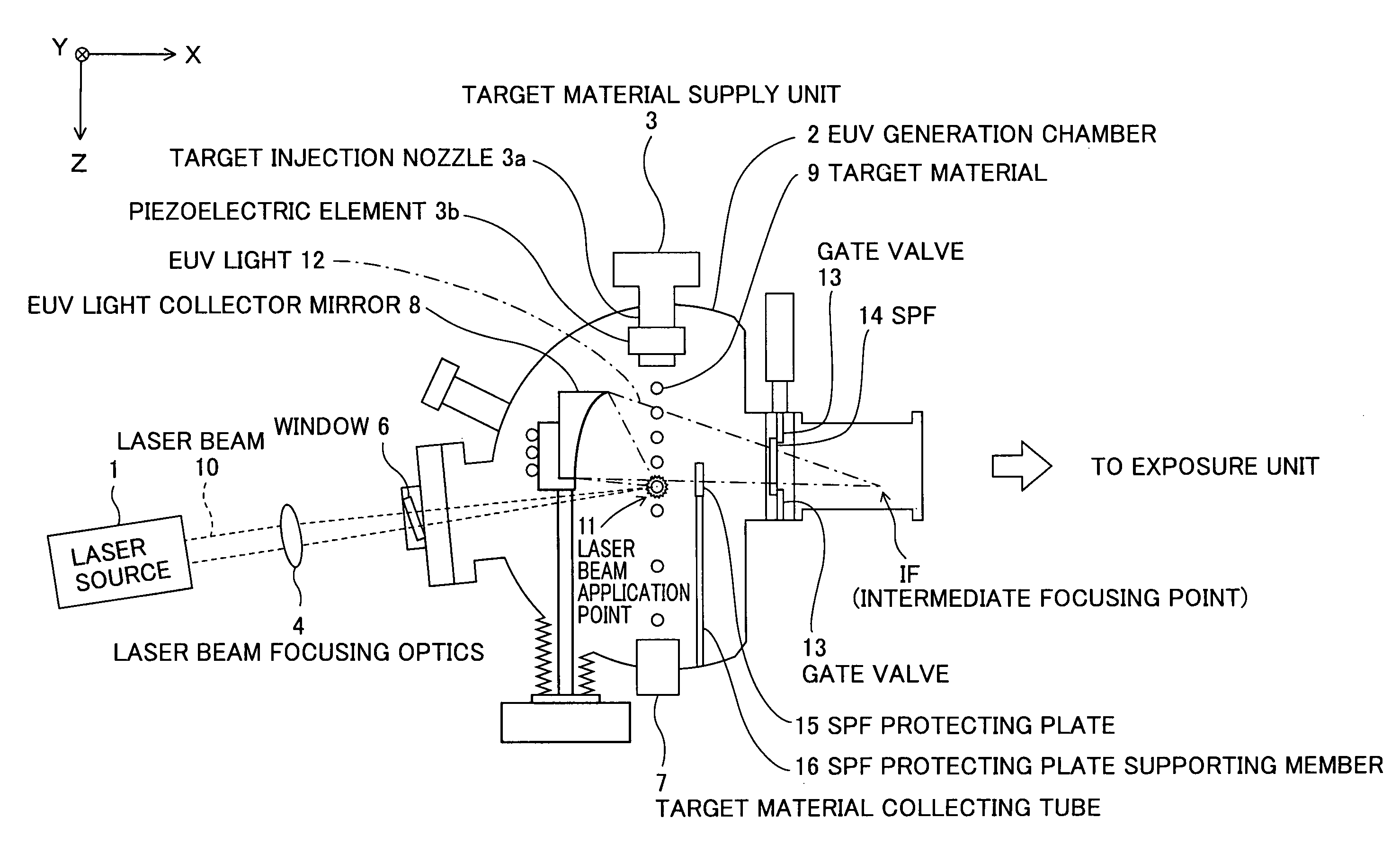
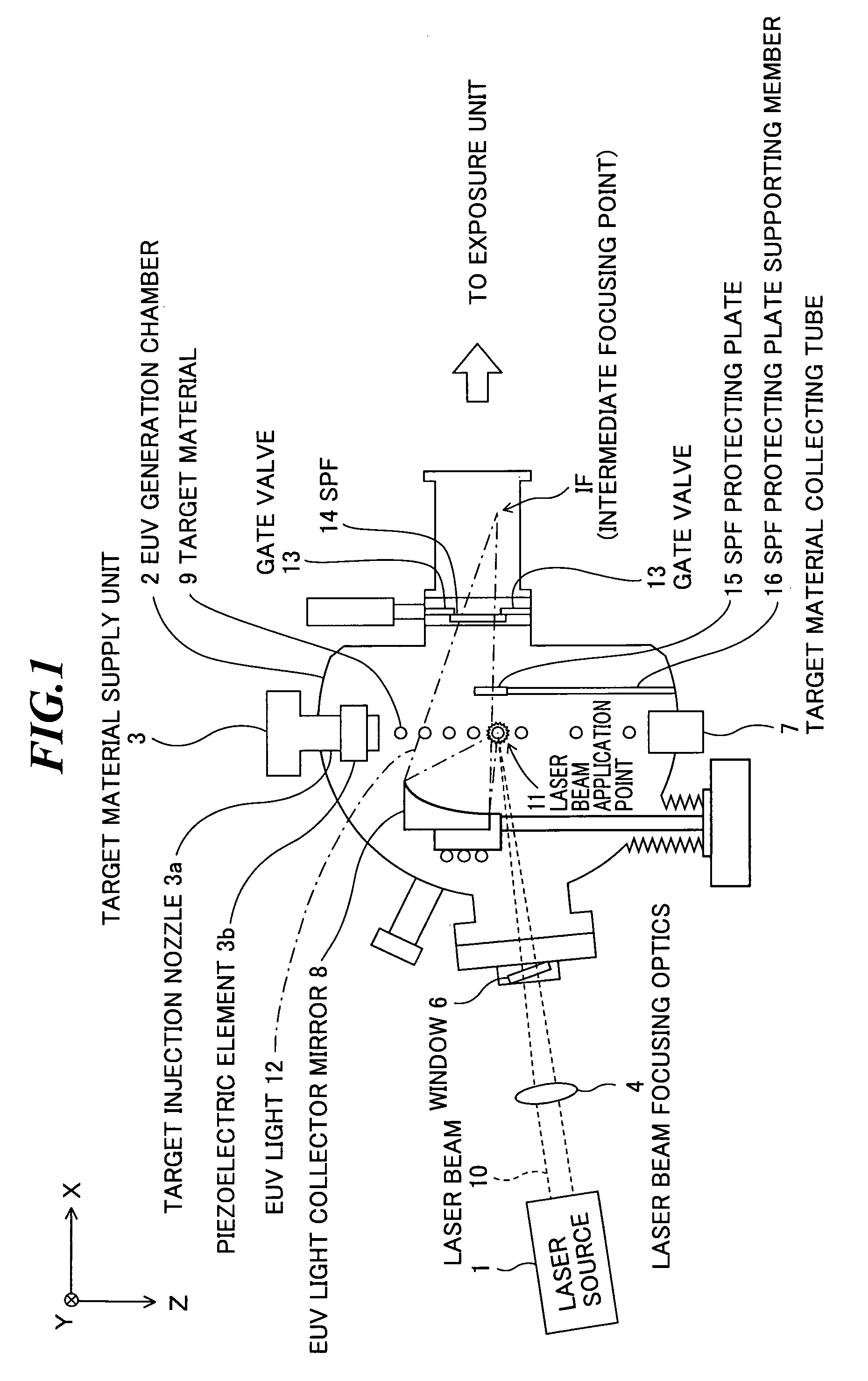
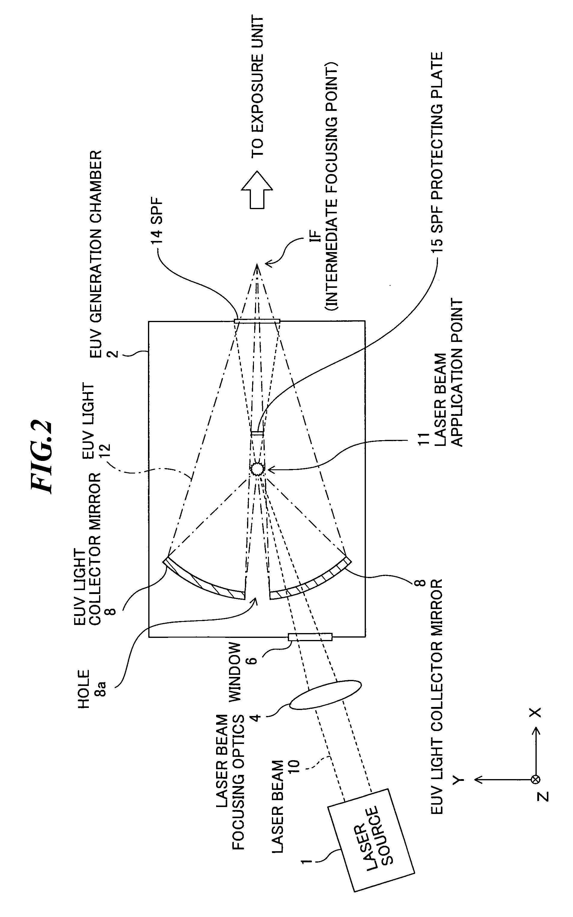
[0050]FIG. 2 is a schematic diagram showing the EUV light source apparatus according to the first embodiment. In FIG. 2, the target material supply unit 3, the target material collecting tube 7, the gate valve 13, and the SPF protecting plate supporting member 16 (see FIG. 1) are omitted, and it is assumed that the target material is injected perpendicularly to the paper surface of the drawing. Further, FIG. 3 is an enlarged view of the EUV light collector mirror 8, the laser beam application point 11, the SPF 14, and the SPF protecting plate 15 in FIG. 2.
[0051]As shown in FIG. 2, the laser beam 10 outputted from the laser source 1 toward the upper right in the drawing is collected by the laser beam focusing optics 4, and enters the EUV generation chamber 2 through the window 6. The laser beam 10 that has entered the EUV generation chamber 2 through the window 6 passes through the depth si...
second embodiment
[0059]Next, an EUV light source apparatus according to the present invention will be explained.
[0060]FIG. 4 is a schematic diagram showing the EUV light source apparatus according to the second embodiment. In FIG. 4, the target material supply unit 3, the target material collecting tube 7, the gate valve 13, and the SPF protecting plate supporting member 16 (see FIG. 1) are omitted, and it is assumed that the target material is injected perpendicularly to the paper surface of the drawing. Further, FIG. 5 is an enlarged view of the EUV light collector mirror 8, the laser beam application point 11, the SPF 14, and the SPF protecting plate 15 in FIG. 4.
[0061]In the above explained EUV light source apparatus according to the first embodiment, the SPF protecting plate 15 is provided so as to be substantially orthogonal to the line connecting the laser beam application point 11 and the IF (intermediate focusing point) (see FIGS. 2 and 3).
[0062]On the other hand, in the EUV light source ap...
third embodiment
[0076]Next, an EUV light source apparatus according to the present invention will be explained.
[0077]FIG. 6 is a schematic diagram showing the EUV light source apparatus according to the third embodiment. In FIG. 6, the target material supply unit 3, the target material collecting tube 7, the gate valve 13, and the SPF protecting plate supporting member 16 (see FIG. 1) are omitted, and it is assumed that the target material is injected perpendicularly to the paper surface of the drawing.
[0078]In the third embodiment, an SPF 16 having a larger thickness and higher strength than the SPF 14 is provided in place of the SPF 14 in the above-explained EUV light source apparatus according to the first embodiment (see FIG. 2). Thereby, deterioration and / or breakage of the SPF 16 can be reduced.
PUM
 Abstract
Description
Claims
Application Information
 - R&D
- Intellectual Property
- Life Sciences
- Materials
- Tech Scout
- Unparalleled Data Quality
- Higher Quality Content
- 60% Fewer Hallucinations
Browse by: Latest US Patents, China's latest patents, Technical Efficacy Thesaurus, Application Domain, Technology Topic, Popular Technical Reports.
© 2025 PatSnap. All rights reserved.Legal|Privacy policy|Modern Slavery Act Transparency Statement|Sitemap|About US| Contact US: help@patsnap.com