
Data centers

Inactive Publication Date: 2008-09-04
STEVENS JASON
View PDF28 Cites 68 Cited by
  • Summary
  • Abstract
  • Description
  • Claims
  • Application Information

AI Technical Summary

Benefits of technology

[0014]Adopting this approach, heat can be efficiently transported away from the heat producing component by the heat conducting element to the cooling liquid without the need to pipe the cooling liquid individually to the heat producing components. Where this approach is adopted in a data center environment, as the cooling liquid can subsequently be used to transport the heat away from the vicinity of the data center equipment, the air conditioning requirements for the data center can be significantly less than conventional installations.
[0016]The inner end portions of the heat conducting elements may extend inside the conduit so that they are immersed in the cooling liquid. In some embodiments, the inner end portions of the heat conducting elements extend across substantially the whole width of the conduit to maximise the length of the inner end portion that is immersed in the cooling liquid. The inner ends of the heat conducting elements may be (thermally) connected to heat sinks over which the cooling liquid flows inside the conduit, the heat sinks having a larger surface area than the heat pipe(s) they are connected to. This can increase the rate at which heat is transferred to the cooling liquid.
[0029]Additionally, or alternatively, other support members or structure may be provided for the electronic components to reduce (or substantially remove all of) the load on the heat pipes or other conducting elements.
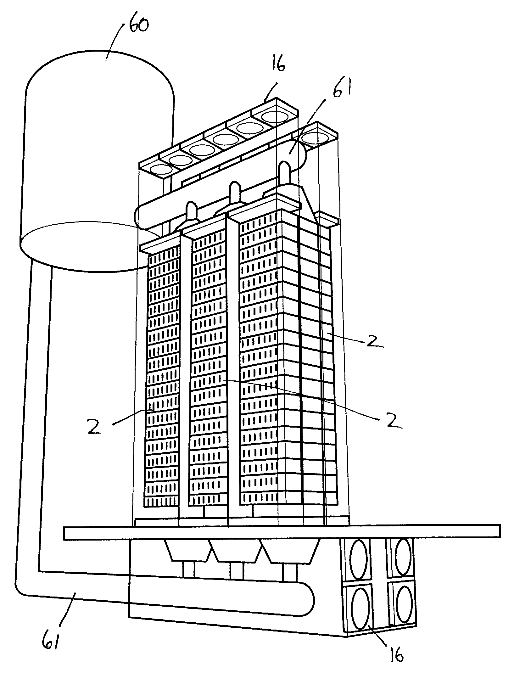
[0043]The cooling system of this aspect may include any one or more of the features set out above in the context of the first aspect of the invention. For example, the heat conducting elements (which in some embodiments are heat pipes) may serve as part of the support structure for the processors. This can provide a very compact overall structure for the processor stack, enabling higher density of processors than is possible with conventional rack-based data centers.
[0066]The efficient cooling of the processor stacks means they can be arranged closely to one another in the data center and may be more densely packed than conventional rack arrangements. The limit will typically be imposed by a need to allow physical access to the processor stacks, e.g. for maintenance.

Problems solved by technology

The rack mounted servers must be cooled to remove the excess heat generated by their processors and other components, so complex air conditioning systems are required to maintain the desired temperature and humidity in the room.
These air conditioning units have large power demands, to the extent that in some cases it is the capacity of local electricity grids that place limits on the maximum size of data centers.
However, despite improvements in processor efficiency, increases in processing power are inevitably accompanied by increases in the heat generated by the servers' processors and limits are quickly reached beyond which it becomes difficult to effectively cool the processors using conventional approaches because of the load that is put on the air conditioning systems and subsequent costs.
In effect, limitations in the ability to cool processors place serious physical limits on the capacity of data centers, which if exceeded can cause problems including hot servers potentially leading to malfunctions, reduced mean time before failure (MTBF) and unexpected thermal shutdowns.
Moreover, this duplicated equipment is sized to account for peak loads, which are generally experienced very infrequently, meaning much of the capacity of the system remains idle whilst still requiring cooling effort.
The increasing popularity of virtualisation of servers, which increases loads on processors, can only make things worse.
However, to bring the cooling liquid close to the processors (the components that produce the most heat), in order to minimise the reliance on convection to transport heat from the processors to the cooling liquid, intricate pipe work is needed, complicating server maintenance.

Method used


Image

  • Data centers
  • Data centers
  • Data centers

Examples


Embodiment Construction

Data Processor Stack—‘CoreStalk’

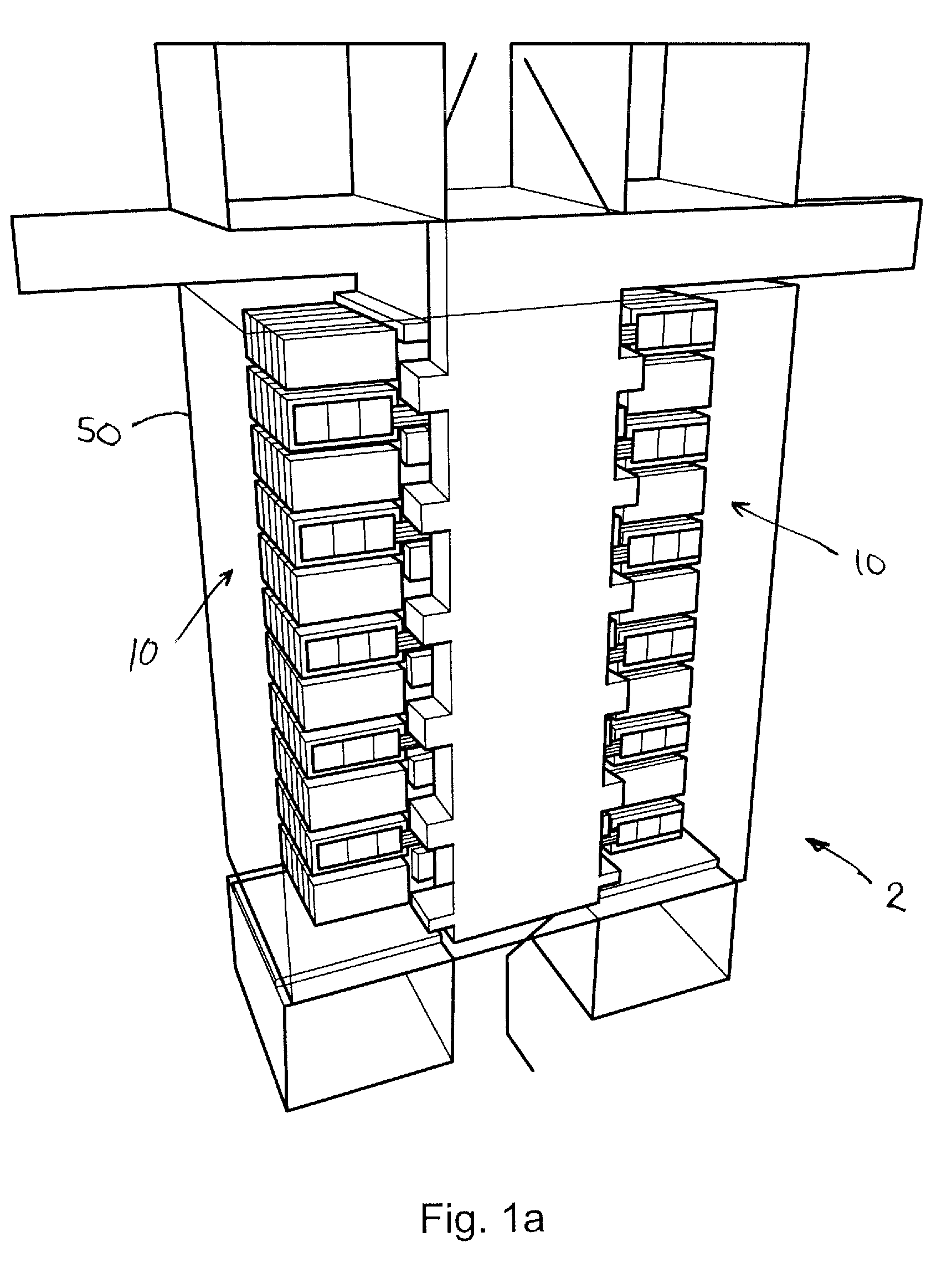
[0074]FIG. 1a illustrates a data processor stack 2, referred to as a ‘CoreStalk’ in the following, for use in a data center environment. As explained in more detail below, the stack 2 is built around a novel cooling system that uses a liquid cooling medium (in this example water) as the primary mechanism for transporting heat away from the stack 2. However, to avoid the need for intricate pipe work with a server or other mechanisms to bring the cooling water into close proximity with heat generating components (especially processors) in the stack 2, heat is conducted from these components to the cooling water by heat pipe conductors 4 (see FIG. 1b) that extend laterally from a central column 6 of cooling water (see FIG. 1c) in the stack 2 out to the components.

[0075]In more detail, and with reference to the figures, the CoreStalk concept is aimed at bringing computer processors closer to a better cooling solution, rather than the more difficult and ex...


PUM


Abstract

The invention is concerned with new approaches to cooling processing equipment in data centers. A cooling system is described herein that is suitable for cooling processing equipment in data centers. The cooling system includes a vertical conduit carrying a cooling liquid and an array of elongate heat conducting elements, such as heat pipes, extending laterally outwardly from the conduit. An inner end portion of each heat conducting element is in thermal contact with cooling liquid flowing in the conduit and an outer end portion of each heat conducting element is adapted for conductive thermal contact with at least one heat producing electronic component.

Description

FIELD OF THE INVENTION[0001]The present invention relates to data center technology. It is particularly concerned with new approaches to cooling processing equipment in data centers.BACKGROUND[0002]Conventional data centers occupy large rooms with closely controlled environmental conditions. The data storage and processing equipment generally takes the form of servers, which are mounted in standard (e.g. 19 inch) rack cabinets, the cabinets being arranged in a series of rows in the room. The rack mounted servers must be cooled to remove the excess heat generated by their processors and other components, so complex air conditioning systems are required to maintain the desired temperature and humidity in the room. These air conditioning units have large power demands, to the extent that in some cases it is the capacity of local electricity grids that place limits on the maximum size of data centers.[0003]There is an ever increasing demand for data storage and processing capacity. Part...

Claims


Application Information

Patent Timeline
IPC IPC(8): H05K7/20F28F1/00
CPCH05K7/20763F28D15/0275
Inventor STEVENS, JASON
Owner STEVENS JASON
Learn More