
Method and apparatus for secure transactions

Inactive Publication Date: 2008-08-28
KEY INNOVATIONS
View PDF6 Cites 73 Cited by
  • Summary
  • Abstract
  • Description
  • Claims
  • Application Information

AI Technical Summary

Benefits of technology

[0020]To overcome limitations in the prior art, and to overcome other limitations that will become apparent upon reading and understanding the present specification,

Problems solved by technology

Merchants operating with slim profit margins are especially interested in PIN-based debit card transactions because signature based interchange fees consume a large portion of the already low profit.
However, the security of the PIN is subject to strict controls as promulgated by the payment card industry (PCI) data security standard (DSS) and PCI pin entry device (PED) compliance.
In other applications, however, the integrated PED concept may be too restrictive and cumbersome to meet market demands.
In particular, designing or retrofitting an integrated PED into a kiosk or vending machine may not be possible due to functionality that is provided by the kiosk or vending machine.
Such solutions, however, may be cost prohibitive due to the performance that is required to be provided by each subsequent security processor, which inherently increases the cost of each modular component.
The conventional modular approach, therefore, needlessly increases cost and complexity.
In response, the EPP must transmit the card holder's identifying information as clear text, since the credit network does not support decryption capabilities.
Thus, use of conventional EPPs to achieve a modular solution is not PCI compliant, since a spoofing attack on the EPP may cause the EPP to enter the clear text mode while the user is being queried for his or her PIN.
In such an instance, software / hardware installed by the attacker may cause unauthorized prompts to appear on the display, which cause the card holder to enter personal information, such as the card holder's PIN, to compromise the card holder's banking information.

Method used


Image

  • Method and apparatus for secure transactions
  • Method and apparatus for secure transactions
  • Method and apparatus for secure transactions

Examples


Embodiment Construction

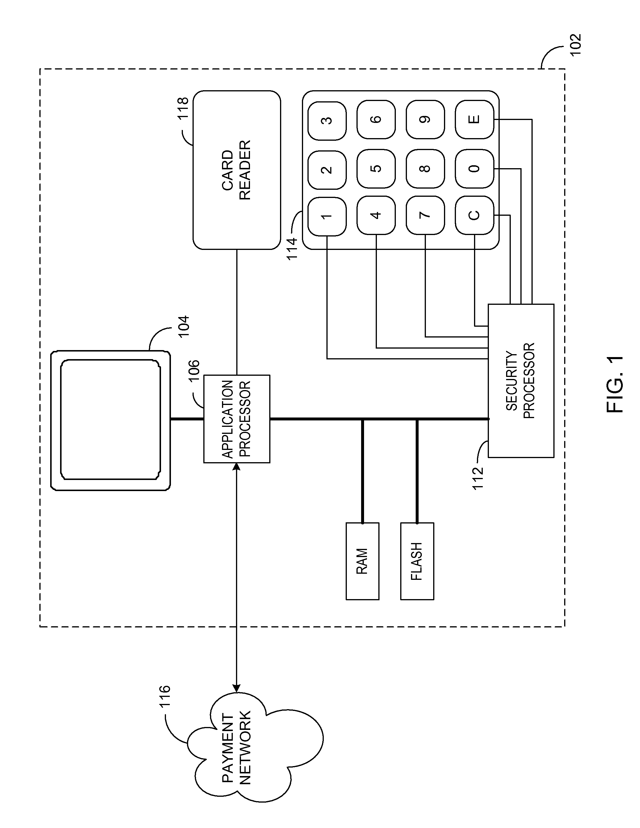
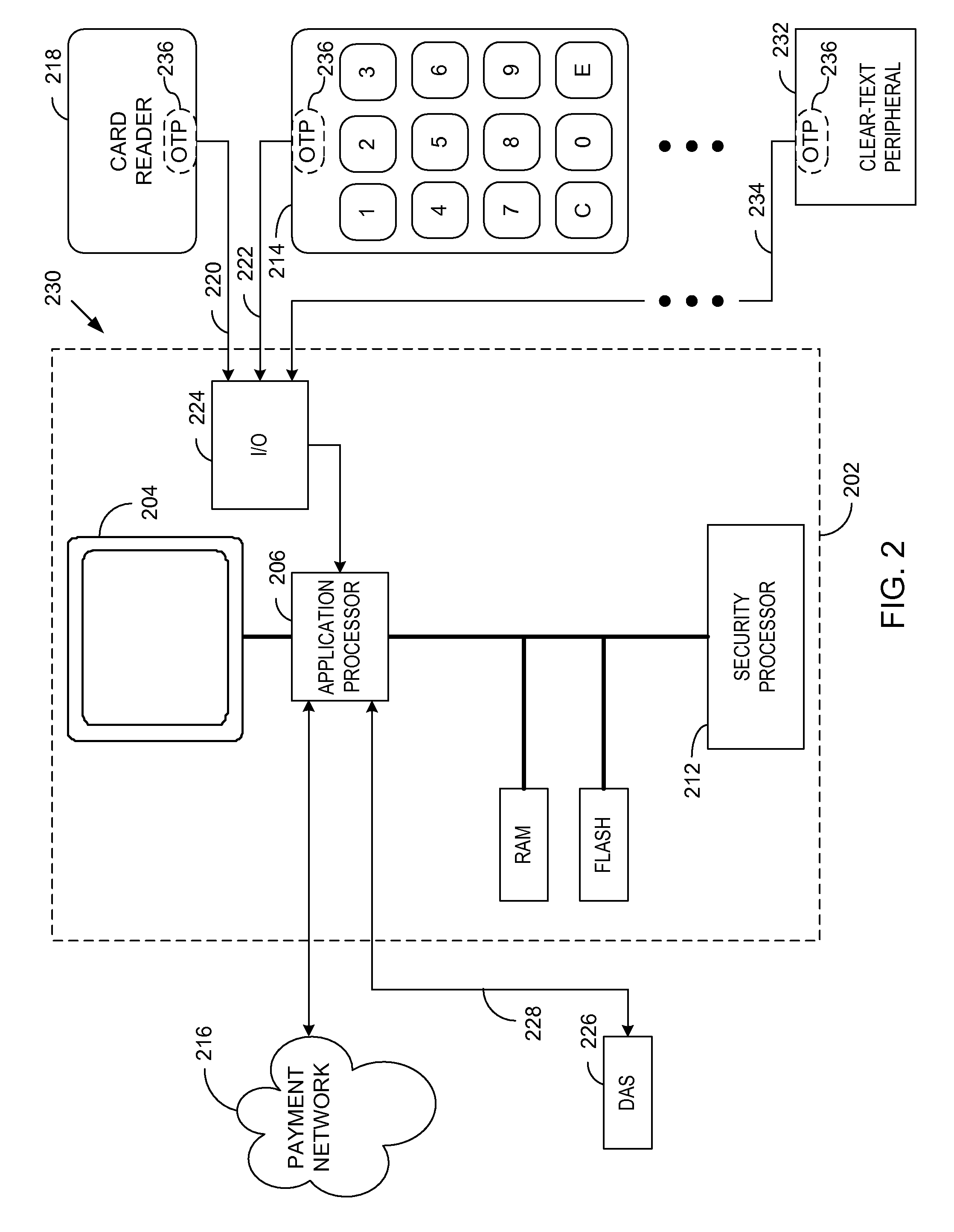
[0033]Generally, various embodiments of the present invention are applied to a modular, secure terminal that secures data transmission and is compliant with the payment card industry (PCI) PIN entry device (PED). In a first embodiment, a security processor is combined with an application processor and a display into a secure display control unit (SDCU) that provides tamper resistance and other security measures that are PCI PED compliant and that establish the same security as a fully integrated PED. Modular secure I / O devices, such as a secure key pad (SKP) and a secure card reader (SCR), are interfaced to the SDCU via a wired, or wireless, medium so as to facilitate secure data transfer from the SKP / SCR to the SDCU during a POS transaction, or other transaction that requires secure data entry. In other embodiments, the SKP and SCR may be combined into a single modular unit.

[0034]The SKPs and SCRs do not require the same processing power as the SDCU, since the SKPs and SCRs are not...


PUM


Abstract

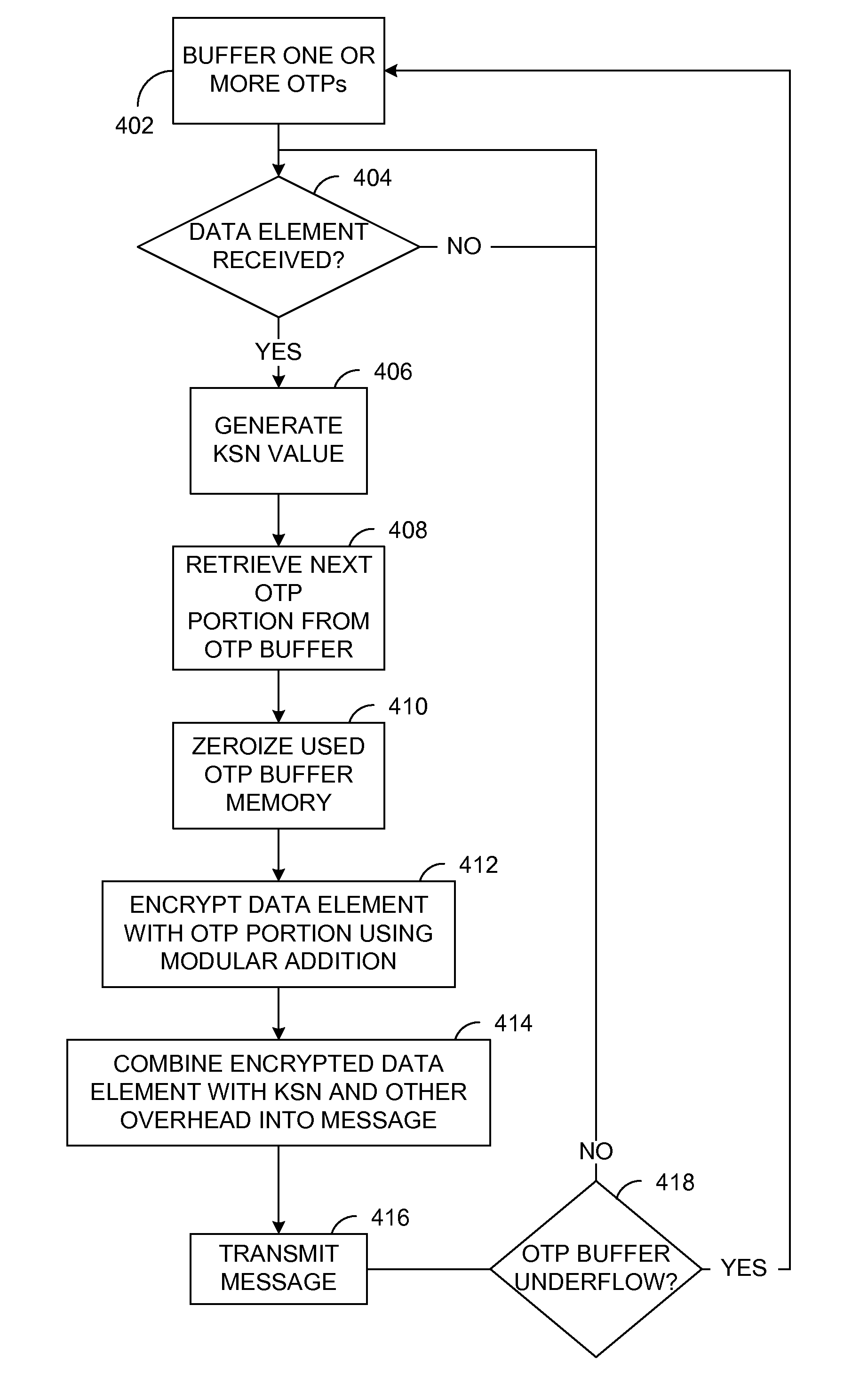
A method and apparatus is provided for secure terminals that facilitate secure data transmission and are compliant with the payment card industry (PCI) data security requirements. A security processor is combined with an application processor and a display into a secure display control unit (SDCU) that provides tamper resistance and other security measures. Modular secure I / O devices are interfaced to the SDCU via a wired, or wireless, medium so as to facilitate secure data transfer to the SDCU during a point-of-sale (POS) transaction or other transaction that requires secure data entry. The secure I / O devices implement one-time-pad (OTP) encryption, where the random keys, or pads, are generated by a derived unique key per transaction (DUKPT) generator. Other embodiments facilitate interconnection of the secure I / O devices to a hardware security module (HSM) or a personal computer (PC) while maintaining a high level of data security.

Description

FIELD OF THE INVENTION[0001]The present invention generally relates to electronic transactions, and more particularly to secure electronic transactions.BACKGROUND OF THE INVENTION[0002]With the advent of signature based payment media, such as credit cards and signature based debit cards, the ability to electronically authorize and settle transactions has virtually eliminated the need for cash. In particular, the customer's banking information may be derived from the magnetic stripe of the credit card using a magnetic stripe / swipe reader (MSR) or other means such as radio frequency identification (RFID). The necessary authorization and settlement functions may then be electronically executed to complete the customer's purchase. Authentication of the credit / debit card holder may be verified by the merchant through comparison of the customer's signature on the back of the credit card to the signature on the merchant's receipt. Such a signature not only authenticates the credit card hol...

Claims


Application Information

Patent Timeline
IPC IPC(8): G06Q40/00H04L9/10
CPCG06F21/83G06F21/85G06Q20/108G06Q20/20G06Q20/382G06Q20/3829H04L2209/56G07F7/1016G07F7/1025G07G1/12H04L9/0656H04L2209/127G07F7/1008
Inventor SPIKER, NORMAN S.WALTERS, PAUL M.
Owner KEY INNOVATIONS
Learn More