
Analogue Display Member Made of Crystalline Material, Timepiece Fitted Therewith and Method for Fabricating the Same

a technology of crystalline materials and display members, which is applied in the field of analogue display members, can solve the problems of reducing the creativity of timepiece designers, reducing the dimensional precision of timepieces, and difficult to obtain satisfactory dimensional precision with machining and die stamping techniques. , to achieve the effect of reducing the mass of display members, reducing unbalance and inertia, and being easy to fabrica

Active Publication Date: 2008-08-21
MONTRES BREGUET
View PDF3 Cites 19 Cited by
  • Summary
  • Abstract
  • Description
  • Claims
  • Application Information

AI Technical Summary

Benefits of technology

[0011]The display member according to the invention has the advantage of being able to be easily fabricated using technology proven in microelectronics for fabricating integrated circuits and in micromechanics for fabricating microstructures.
[0012]Silicon has the advantage of being very light, since its density is approximately 2.49 kg / dm3, which minimises the mass of the display member, and thus problems of inertia and unbalance, in particular when it takes the form of a hand. Moreover, the reduction in unbalance and inertia of the display member has a positive influence on the sizing of the display member drive means and on the energy consumption of said drive means.
[0024]This method is easy to implement to mass-produce precise, light pieces.

Problems solved by technology

The fabrication of a hand for use as a display member in a timepiece is particularly complex, in particular when the hand is to be fitted to a top of the range timepiece, for which the hand has to have a particularly polished surface appearance, possibly with facets.
However, satisfactory dimensional precision can still not be obtained with the machining and die stamping techniques for these materials, and additional operations of deburring, polishing, etc are required to obtain the final shape of the hand.
Further, current hand fabricating techniques do not allow all desired forms to be achieved, thereby curbing the creativity of timepiece designers.

Method used


Image

  • Analogue Display Member Made of Crystalline Material, Timepiece Fitted Therewith and Method for Fabricating the Same
  • Analogue Display Member Made of Crystalline Material, Timepiece Fitted Therewith and Method for Fabricating the Same
  • Analogue Display Member Made of Crystalline Material, Timepiece Fitted Therewith and Method for Fabricating the Same

Examples


Embodiment Construction

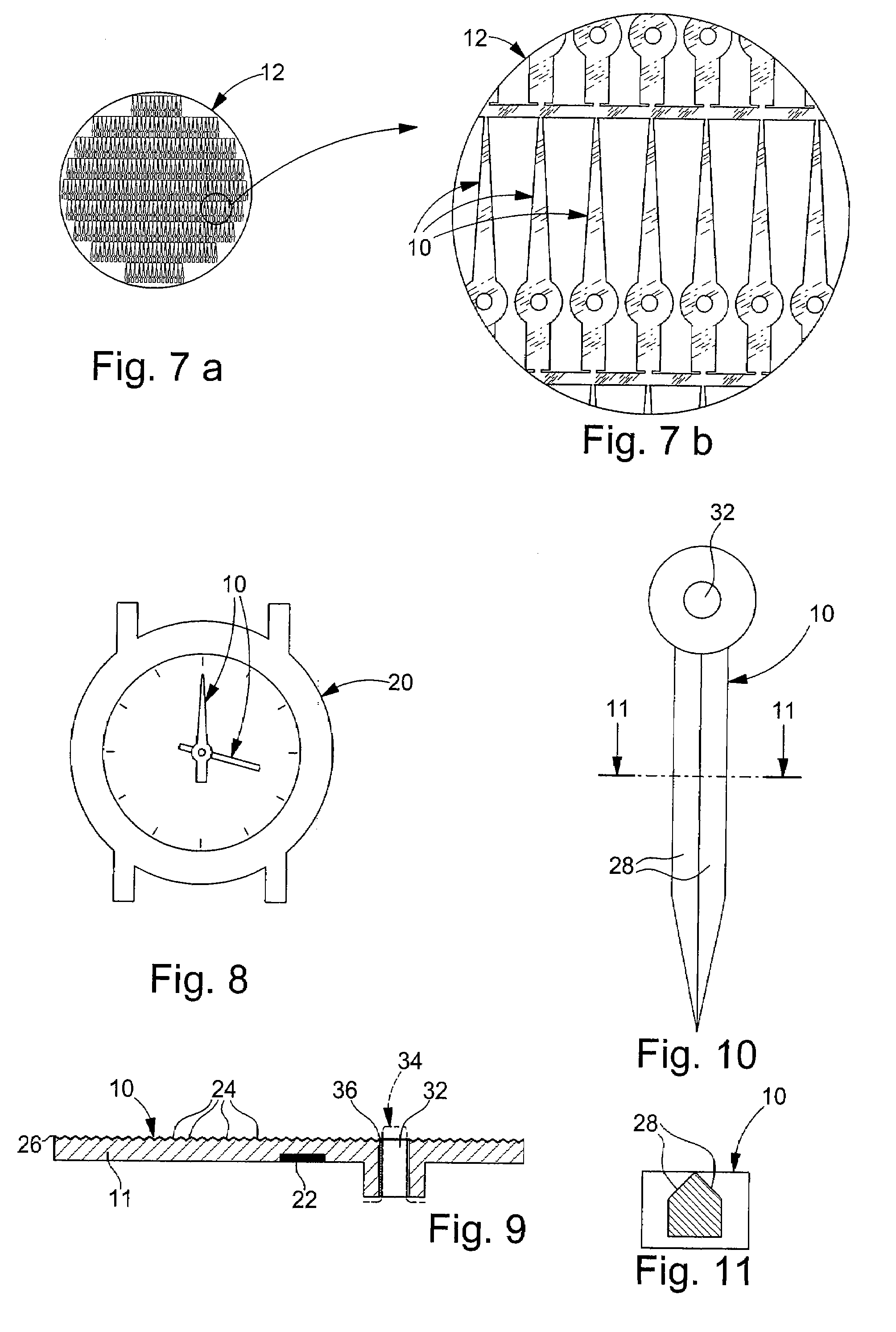
[0043]FIGS. 1 to 7 show several steps of a method for fabricating analogue display members 10 in accordance with the teaching of the invention.

[0044]Analogue display members 10 are here hands 10, one example of which is shown schematically in FIG. 9.

[0045]In accordance with the teaching of the invention, each hand 10 includes a main body 11 which is made of silicon based crystalline material.

[0046]“Silicon based crystalline material” here means a crystalline material containing silicon such as monocrystalline silicon, polycrystalline silicon and quartz.

[0047]Preferably, hand 10 according to the invention is micro-machined in a monocrystalline silicon plate 12 like those that are used to make integrated electronic circuits, such plates being generally called “wafers”.

[0048]Advantageously, a series of several hands 10 is made in the same silicon wafer 12, in accordance with a method called “batch processing”, using techniques derived from microelectronics which enable mechanical micro...


PUM


Abstract

The invention proposes an analogue display member (10) fitted to a timepiece, of the type including a main body in which an arbour hole is arranged, characterized in that the main body is made of silicon based crystalline material. The invention also proposes a timepiece provided with such a display member (10). The invention also proposes a method of fabricating analogue display members (10) to be fitted to timepieces, each analogue display member (10) including a main body, characterized in that it includes at least one step of micro-machining a wafer of silicon based crystalline material to form at least one main body in said material.

Description

[0001]This is a National Phase Application in the United States of International Patent Application No. PCT / EP2006 / 061949 filed May 1, 2006, which claims priority on European Patent Application No. 05103979.0, filed May 12, 2005. The entire disclosures of the above patent applications are hereby incorporated by reference.FIELD OF THE INVENTION[0002]The invention concerns an analogue display member such as a timepiece hand.[0003]The invention also concerns a timepiece and a method of fabricating a display member.BACKGROUND OF THE INVENTION[0004]The fabrication of a hand for use as a display member in a timepiece is particularly complex, in particular when the hand is to be fitted to a top of the range timepiece, for which the hand has to have a particularly polished surface appearance, possibly with facets.[0005]Currently, hands are fabricated in brass, steel, gold, aluminium, or in a special alloy. They can be galvanically treated, covered with paint, oxidised or untreated if the ma...

Claims


Application Information

Patent Timeline
IPC IPC(8): G04B19/06
CPCB81C1/00246B81C99/008G04B19/042Y10T74/1587G04D3/0046G04D3/0069G04B45/02G04B19/04G04D3/00
Inventor MEISTER, PIERRE-ANDREZANETTA, ANDREFLEURY, EMMANUELBLONDEAU, FABIEN
Owner MONTRES BREGUET
Learn More