
Lightguide arrangement and related applications

a technology of lightguides and lightguides, applied in the field of optics, can solve the problems of difficult light management in order to achieve uniform keypad lighting, impractical thickness of keypad arrangements, defects and damage of dome sheet layers, etc., and achieve the effect of reducing the overall optical efficiency of the assembly, increasing the rigidity of the actuating members, and increasing the optical efficiency

Active Publication Date: 2008-08-07
MODILIS HLDG LLC
View PDF20 Cites 59 Cited by
  • Summary
  • Abstract
  • Description
  • Claims
  • Application Information

AI Technical Summary

Benefits of technology

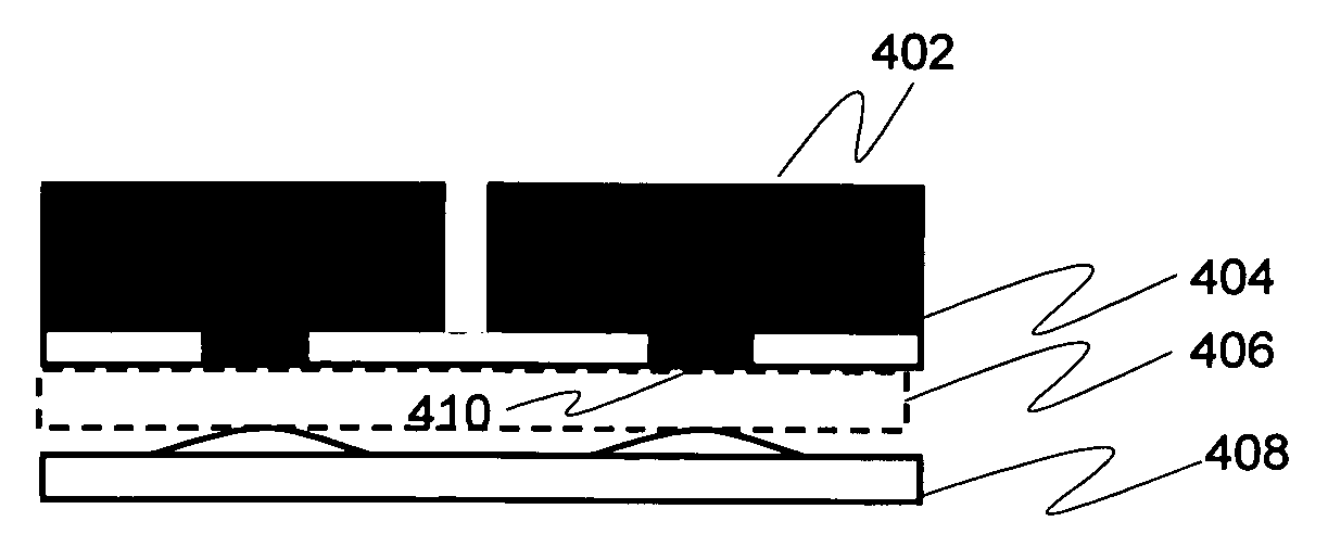
[0016]a dome sheet disposed on opposite side of the lightguide, the dome sheet including a plurality of bendable domes positioned so that upon depressing a predetermined key, a corresponding, predetermined dome is deformed by pressure introduced by the rigid actuation member of the predetermined key via the lightguide in order to perform an associated event such as opening or closing an electrical switch,wherein at least the portion of the lightguide residing between the predetermined dome and the predetermined key may be arranged at least optically substantially continuous, thin and typically flexible so as to provide improved tactile feeling to a user of the keypad upon key actuation. Additionally, the lightguide may provide a protecting layer for the dome sheet against the rigid actuation member.
[0019]In a further aspect of the present invention a stiffer and optionally optically functional, thinner element may be used to support a flexible, e.g. elastic, and optically substantially transparent lightguide element by integrating the two prior to or upon roll-to-roll embossing of micro-optic surface relief forms in the integrated entity so as to manufacture an integrated, flexible lightguide element substantially free or at least having a reduced amount of artifacts in the embossed micro-optic surface relief forms in contrast to artifacts arising from merely roll-to-roll embossing the flexible element.
[0021]The utility of embodiments of the present invention may arise from a plurality of issues depending on each particular embodiment. A thin lightguide according to one aspect of the present invention may be used for creating one or more active indicative and / or decorative illumination effects via interaction between one or more, e.g. two or three, light sources incoupled to the thin lightguide and one or more micro-optic surface relief forms, e.g. different micro-optic patterns, of the lightguide. The thin lightguide may be configured to provide illumination effects, such as gradually or stepwise brightness- and / or color-changing indicators that may be controlled by a host device such as a mobile terminal via associated processing means according to a predetermined criterion; the indicator may be configured to visualize internal status information or e.g. a selected, current parameter value of the device, for example. An indicative illumination effect may further be obtained by utilizing a keymat together with the lightguide. Active decorative effects may be controlled by the host device, may include various symbols, graphical shapes or other forms. Both the effect types may be at least partly defined by the corresponding micro-optic surface relief patterns on the lightguide. Additionally, mask(s) may be used to prevent light entering and / or penetrating predetermined areas. One or more similar or different (e.g. emitting different color) light sources such as LEDs may be applied to provide active brightness (illumination level) and / or color adjustment to the effects (brightness / color fading relative to time and / or location on the lightguide, for example). Various “live” or “animated” effects, such as waterfall or fire shapes, may be obtained. The present invention provides very flexible and integrated solution for active low cost illumination in contrast to conventional indicative and decorative illumination effects that are typically provided with more expensive and complex display solutions.
[0023]A thin keypad assembly may be obtained without introducing apertures in the lightguide for the rigid actuation members such as key plungers. As such apertures typically may also reduce the overall optical efficiency of the assembly, the obtained optical efficiency may be increased by the invention with respect to typical prior art solutions. Further, the obtained tactile feel is good and in many cases improved in relation to prior art solutions; soft / flexible / thin lightguide layers enable delicate pressure transfer through them while the increased rigidity of the actuation members still provides well-targeted pressure on the domes. The lightguide positioned between the domes and the rigid actuation member on the other hand protects the domes from overpressure.
[0024]The multi-purpose lightguide element in accordance with one aspect of the present invention can enable manufacturing application-specific illumination elements both cost-effectively and rapidly, as a more generic, highly directive / collimating light coupling structure may be first manufactured, optionally stored and later tailored (cut to size and optionally otherwise treated, for example) for each application wherein an application-specific optically functional element such as a diffuser, for example, is integrated with the multi-purpose element.

Problems solved by technology

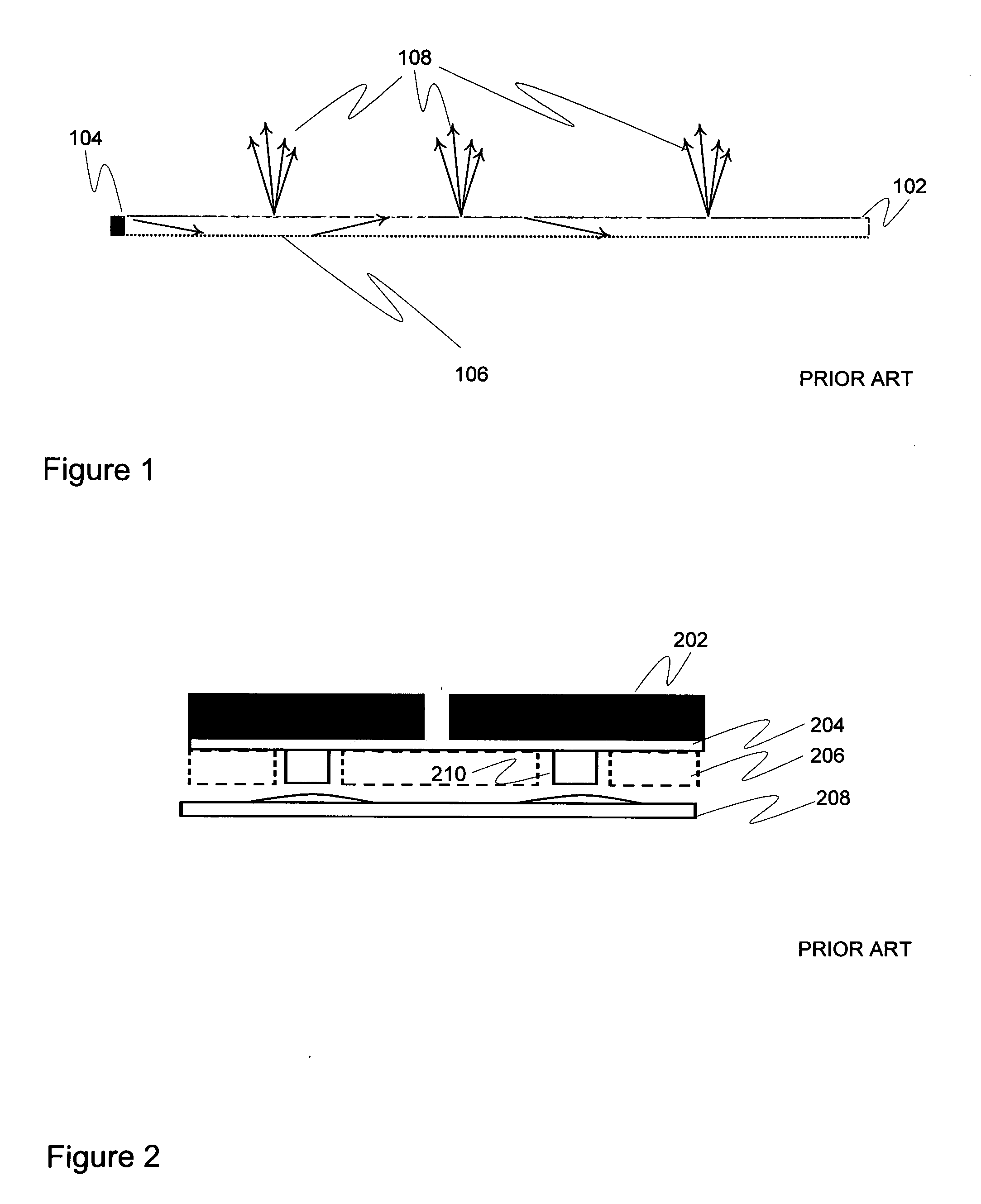
However, these apertures make it difficult to manage light in order to achieve e.g. uniform keypad lighting.
The resulting keypad arrangement may also be impractically thick relative to the initial design goal as the soft material plungers 210 have to be rather thick so as to reach through the thick lightguide 206 and actuate the dome.
Additionally rigid plungers cause defects and damages for the dome sheet layers, thus soft silicone plungers are used.
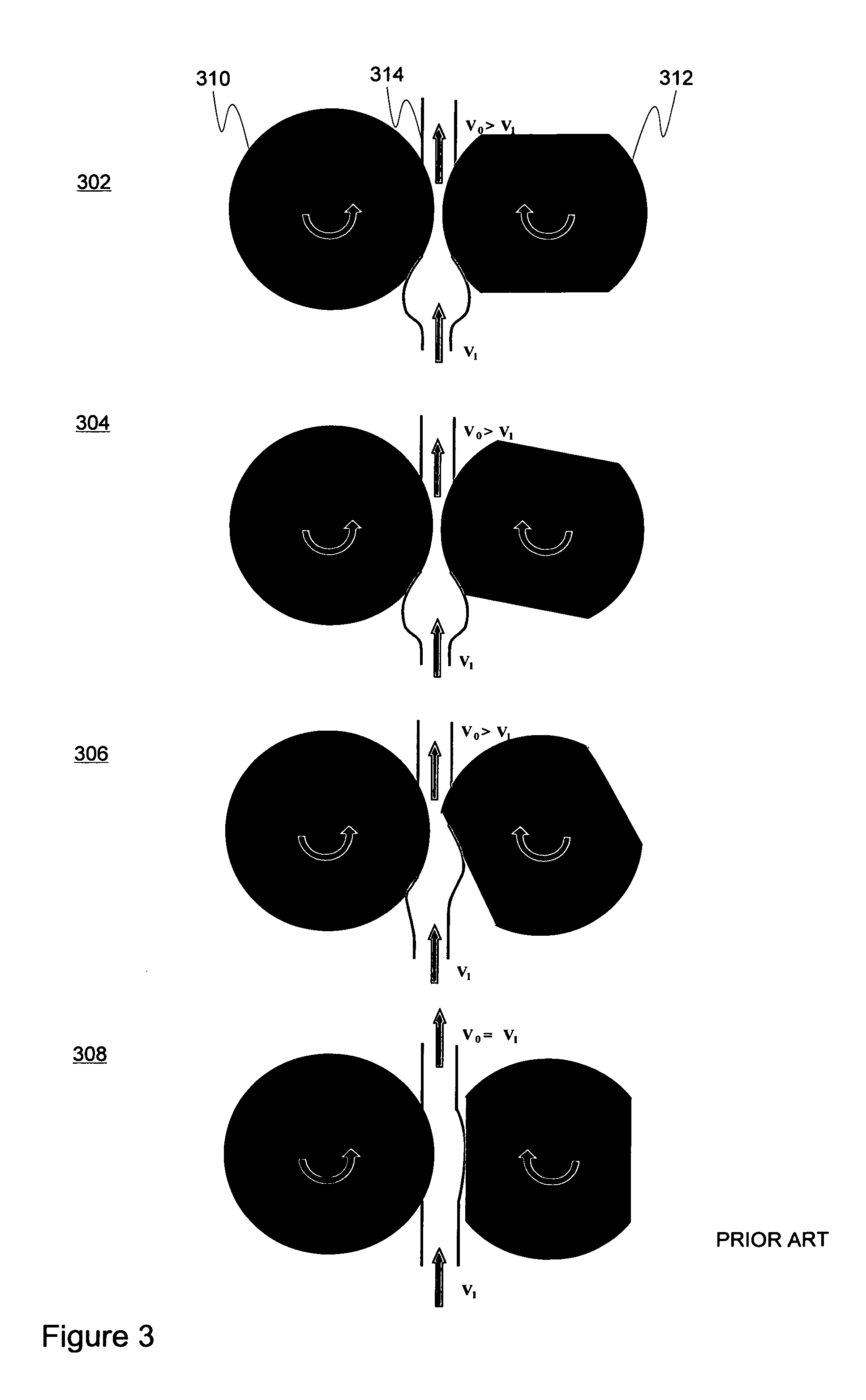
One drawback of many roll-to-roll embossing methods is illustrated in FIG. 3.
Such phenomenon creates artifacts in the replicated optical micro-structures as material 314 deformation cannot be properly taken into account in the replication process.

Method used


Image

  • Lightguide arrangement and related applications
  • Lightguide arrangement and related applications
  • Lightguide arrangement and related applications

Examples


Embodiment Construction

[0073]FIG. 4a illustrates one embodiment of the keypad assembly in accordance with the present invention. The keys may be provided as an aggregate entity, such as a key mat, wherein the independent key forms 402 may include a hard top and rigid, either integral, integrated, or otherwise connected, actuation member, such as a plunger 410 slightly protruding from the key structure towards a lightguide 406 (and an underlying dome of the dome sheet 408) whereas a flexible member 404 such as soft material, e.g. silicone, pieces or a layer may be provided to arrange a predetermined, necessary amount of elasticity required between the adjacent keys so that a desired key 402 may be actuated by the user of the keypad. In this particular example the plunger 410 is substantially as thick or, of substantially same “height”, as the surrounding flexible member 404 forming flat surface as can been observed from the FIG. 4a. As the lightguide 406 is thin and typically flexible, it may be constructe...


PUM

PropertyMeasurementUnit
Coloraaaaaaaaaa
Flexibilityaaaaaaaaaa
Areaaaaaaaaaaa

Abstract

A lightguide arrangement including a substantially thin, lightguide for transporting and coupling light. At least one light source is coupled to the lightguide. A plurality of micro-optic surface relief forms are arranged on the lightguide. The lightguide is configured to produce one or more active indicative and / or decorative illumination effects via interaction between the one or more light sources and the plurality of micro-optic surface relief forms. A keypad assembly including the lightguide and uses of lightguide constructions.

Description

CROSS-REFERENCE TO RELATED APPLICATIONS[0001]This application claims priority to U.S. provisional patent application 60 / 858,708 filed Nov. 14, 2006, and U.S. provisional patent application 60 / 907,210 filed Mar. 26, 2007, the entire contents of the disclosures of which are hereby incorporated by reference.FIELD OF THE INVENTION[0002]Generally the invention relates to optics. In particular, the invention pertains to applications of lightguide arrangements for transporting and coupling light via micro-optic surface relief structures, and to manufacturing such lightguide arrangements.BACKGROUND[0003]Lightguides are typically used for guiding light from light sources in various lighting solutions. The lightguides can be used for display lighting (e.g. backlighting, frontlighting), keypad, keyboard and / or button lighting, interior lighting, and exterior lighting, among other applications. Conventional lightguides that are considered as thin may have a thickness of about 0.8 to about 1.0 m...

Claims


Application Information

Patent Timeline
IPC IPC(8): F21V7/04G09G5/00G06F3/038
CPCB29C59/04H01H2227/00G02B6/0036G02B6/006G02B6/0065G06F3/0202H01H13/83H01H2215/008H01H2219/044H01H2219/056H01H2219/062H01H2221/002H01H2221/05H01H2221/07G02B6/0028G02B6/00G06F3/02H04M1/22
Inventor RINKO, KARI
Owner MODILIS HLDG LLC
Learn More