
Additive For Reducing Torque On A Drill String

a technology of additive and drill string, which is applied in the direction of lubricant composition, chemistry apparatus and processes, base materials, etc., can solve the problems of increasing the toxicity and irritation level of fluids, difficult environmental compliance in specific areas of the world, and high cost, and achieve the effect of reducing the torque of drill string

Inactive Publication Date: 2008-07-10
MI
View PDF1 Cites 10 Cited by
  • Summary
  • Abstract
  • Description
  • Claims
  • Application Information

AI Technical Summary

Benefits of technology

[0006]The present invention is generally directed to fluids useful in reducing the torque of drill string, as well as methods for making and methods of using such fluids. The fluids of the present inve

Problems solved by technology

Although oleaginous-based drilling fluids including the so-called synthetic-based fluids do have performance advantages, drawbacks are higher costs and difficult environmental compliance in specific areas of the world.
These lubricants can increase the toxicity and irritation level of the fluids.
Common difficulties with the above solid lubricants have been the environmental concerns when aqueous based drilling fluids are being used and the loading up of the drilling fluid with solid materials.
Further, it should be appreciated that the addition of solid materials that do not contribute to the weighting of the fluid may result in an underweight fluid raising concerns about blow-out or wall collapse.
A further problem encountered with solid lubricating agents is small diameter apertures present in the valves and other flow and pressure control equipment used may prevent the use of solid particulate lubricating agents because these material block and plug the narrow restrictions.
A more serious concern is that the solids might be difficult to remove from the well bore and thus cause formation damage.

Method used


Image

  • Additive For Reducing Torque On A Drill String
  • Additive For Reducing Torque On A Drill String

Examples


example 1

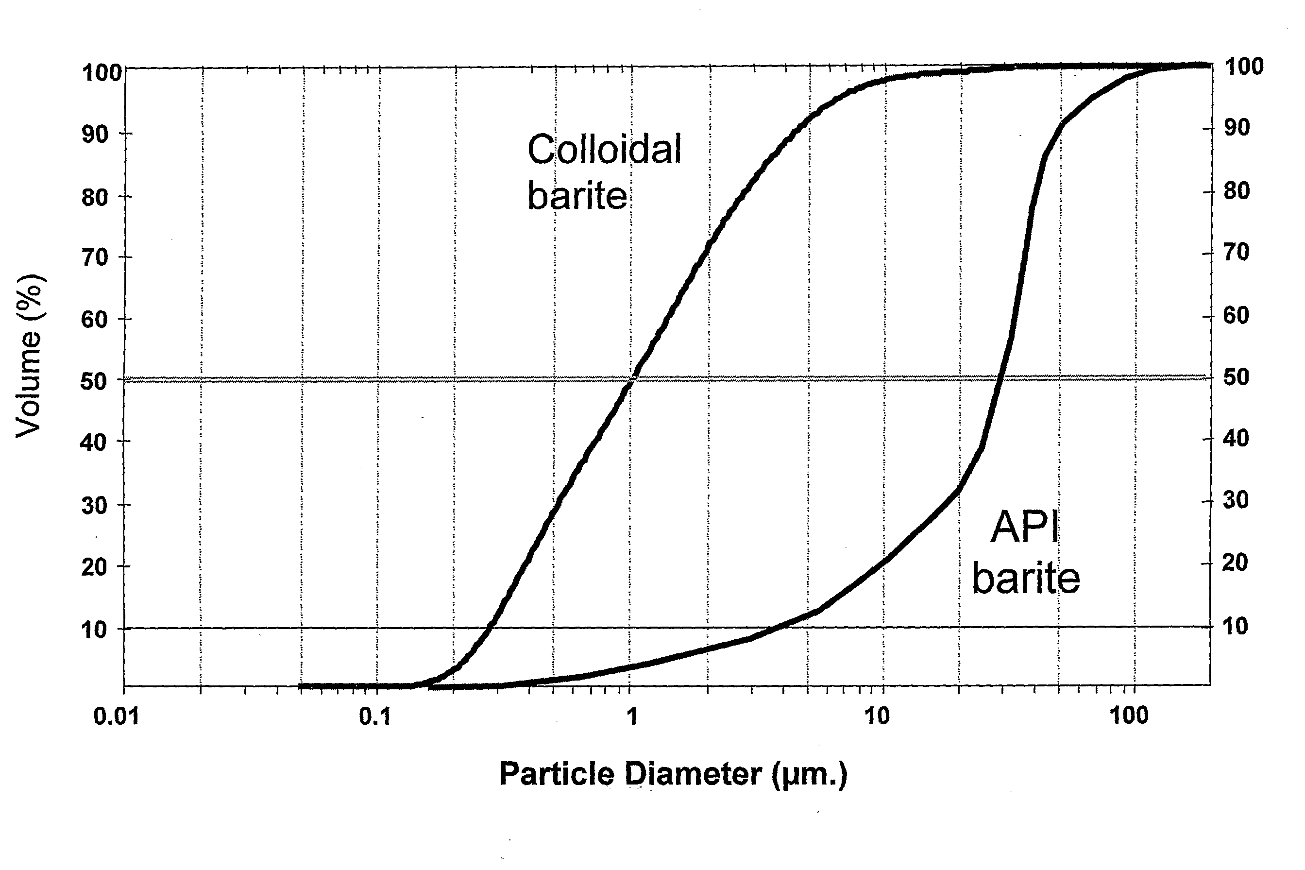
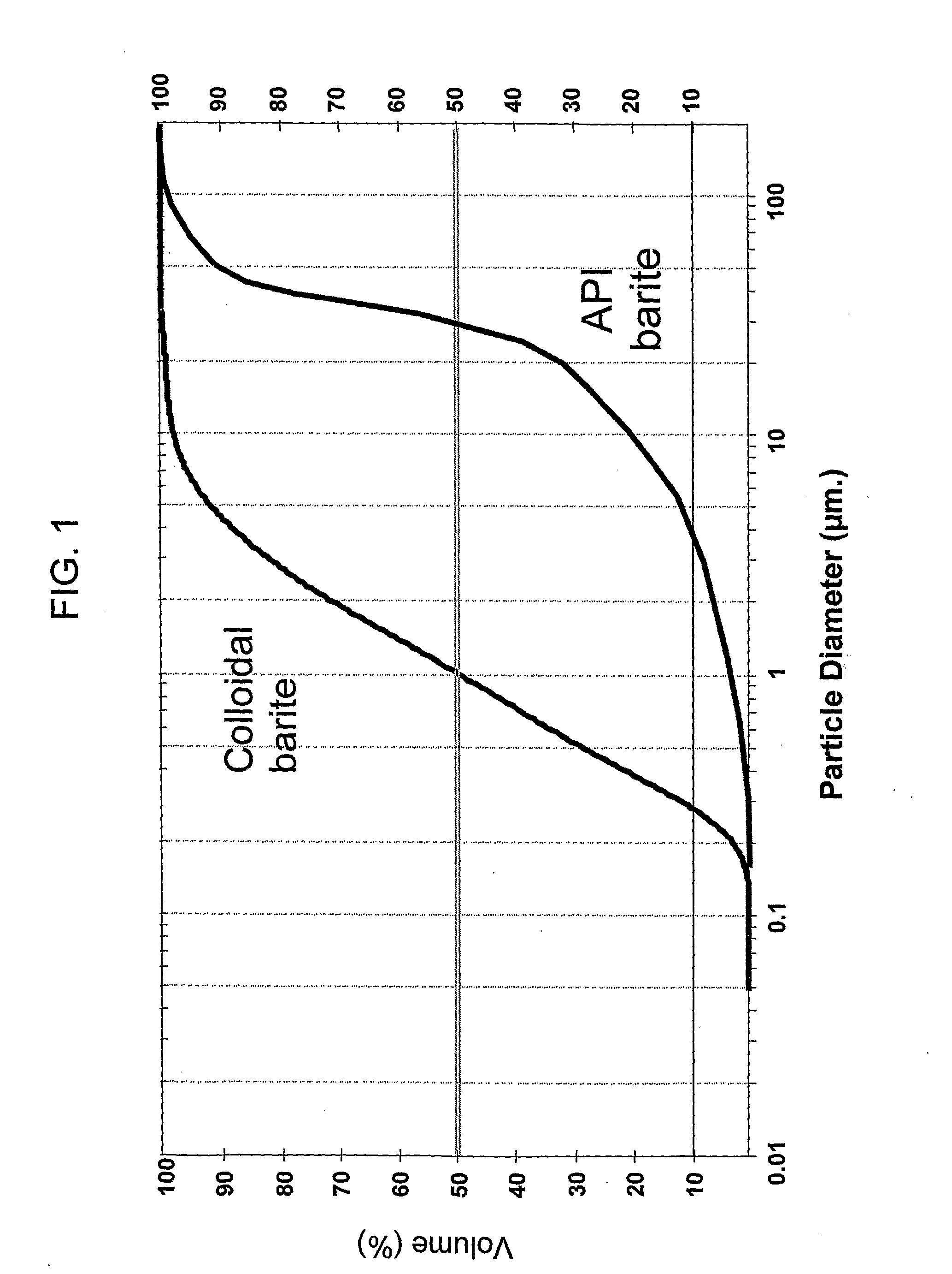
[0030]22 ppg [2.63 g / cm3] fluids based on barium sulfate and water were prepared using standard barite and colloidal barite according to the invention. The 22 ppg slurry of API grade barite and water was made with no gelling agent to control the inter-particle interactions (Fluid #1). Fluid #2 is also based on standard API barite but with a post-addition of two pounds per barrel (5.7 kilograms per cubic meter) IDSPERSE XT. Fluid #3 is 100% new lubricating / weighting agent with 67% w / w of particles below 1 micron in size and at least 90% less than 2 microns. The results are provided in table I.

TABLE IViscosity at various shear rates(rpm of agitation):YieldDial reading or “Fann Units” for:PlasticPoint600200100Viscositylb / 100 ft2#rpm300 rpmrpmrpm6 rpm3 rpmmPa · s(Pascals)12501601249225169070 (34)2265105642611160−55 (−26)365382717322711 (5) 

[0031]For Fluid #1 the viscosity is very high and the slurry was observed to filter very rapidly. (If further materials were added to reduce the flui...

example 21

[0034]Experiments were conducted to examine the effect of the post addition of the chosen polymer dispersant to a slurry comprising weighting agents of the same colloidal particle size. A milled barite (D50˜4 um) and a milled calcium carbonate (70% by weight of the particles of less than 2 μm) were selected, both of which are of similar particle size to the invention related herein. The slurries were prepared at an equivalent particle volume fraction of 0.282 and compared to the product of the present invention (new barite). See table II.

[0035]The rheologies were measured at 120° F. (49° C.), thereafter an addition of 6 ppb (17.2 kg / m3) IDSPERSE XT was made. The rheologies of the subsequent slurries were finally measured at 120° F. (see table III) with additional API fluid loss test.

TABLE IIVolume#MaterialDispersantDensity (ppg)Fractionwt / wt4New baritewhile grinding16.0 [1.92 g / cm3]0.2820.6255Milled baritenone16.0 [1.92 g / cm3]0.2820.6256Milled baritepost-addition16.0 [1.92 g / cm3]0.2...

example 3

[0038]In the following example, two 13.0 ppg fluid formulations are compared, one weighted with conventional API barite and the second weighted with polymer coated colloidal barite (PCC barite) made in accordance with the teachings of the present invention, as a 2.2 sg liquid slurry. Other additives in the formulation are included to provide additional control of pH, fluid loss, rheology, inhibition to reactive shale and claystones. These additives are available from M-I Drilling Fluids.

PRODUCTFluid AFluid BPCC baritelbs / bbl320.0API baritelbs / bbl238.1Freshwaterlbs / bbl175.0264.2Soda Ashlbs / bbl0.40.4Celpol ESLlbs / bbl3.54.2Flotrollbs / bbl3.50Defoam NSlbs / bbl0.40KCllbs / bbl32.936.1Glydril; MClbs / bbl10.510.5Duotec NSlbs / bbl0.11.4

[0039]The fluids were heat aged statically for 48 hrs at 104° F. with the following exemplary results.

Fluid AFluid BFANN 35 Reading (120° F.)InitialAgedInitialAged600 rpm56627365300 rpm36415247200 rpm28334239100 rpm19233129 6 rpm571110 3 rpm4698PV (cps)20212118YP (...


PUM


Abstract

A method of reducing the torque of a drill string used in drilling a subterranean well that includes injecting into the drilling fluid a composition including a base fluid and a polymer coated colloidal solid material. The polymer coated colloidal solid material includes: a solid particle having an weight average particle diameter (d5o) of less than ten microns, and a polymeric dispersing agent coated onto the surface of the solid particle during the cominution (i.e. grinding) process utilized to make the colloidal particles. The polymeric dispersing agent may be a water soluble polymer having a molecular weight of at least 2000 Daltons. The solid particulate material may be selected from materials having of specific gravity of at least 2.68 and preferably the solid particulate material may be selected from barium sulfate (barite), calcium carbonate, dolomite, ilmenite, hematite, olivine, siderite, strontium sulfate, combinations and mixtures of these and other similar solids that should be apparent to one of skill in the art.

Description

BACKGROUND OF THE INVENTION[0001]When oil and gas wells are drilled, fluid formulations with a multitude of properties, including lubricity, are pumped down the well through the drill string and out through nozzles in the drill bit, so that the drilling fluid circulates upward through the annular space between the rotating drill string and the rock formation. The functions of these drilling fluids or “muds” are to cool and lubricate the bit and drill string, to carry the cuttings from the drilling process to the surface, to control and reduce fluid loss into the rock formations, and to support and protect the bore hole until the metal casing can be cemented in place (i.e., create a stable hole).[0002]Mud lubricity (to achieve minimum torque and drag) and mud toxicity (for wells in environmentally sensitive areas, such as offshore drilling) are major concerns when selecting a drilling fluid formulation. Most drilling fluids may be grouped into two major categories: water-based or ole...

Claims


Application Information

Patent Timeline
IPC IPC(8): C10M173/00C10M101/02C10M171/06
CPCC09K8/03C10N2250/12C10M171/06C10M173/00C10M173/02C10M2201/062C10M2201/084C10M2201/102C10M2209/084C10N2210/02C10N2210/08C10N2220/082C10N2230/06C10N2240/00C09K8/035C10N2010/14C10N2020/06C10N2040/00C10N2030/06C10N2010/04C10N2050/015C10N2010/16
Inventor BRADBURY, ANDREWSAWDON, CHRISTOPHEROAKLEY, DOUG
Owner MI
Learn More