Eureka AIR delivers breakthrough ideas for toughest innovation challenges, trusted by R&D personnel around the world.

Liquid ejection apparatus and resist pattern forming method

a technology of resist pattern and liquid ejection, which is applied in the direction of coating, circuit masks, printing, etc., can solve the problems of high manufacturing cost, time and cost, and not necessarily advantageous for creating fine circuits

Inactive Publication Date: 2008-07-03
FUJIFILM CORP
View PDF1 Cites 87 Cited by
  • Summary
  • Abstract
  • Description
  • Claims
  • Application Information

AI Technical Summary

Benefits of technology

[0012]According to this aspect of the present invention, since a resist pattern is formed by accumulation in a single-pass scanning method, which causes the head to scan the wiring substrate by moving the head and the wiring substrate relatively just once through the region of the wiring substrate which is scanned by one scan of the wiring substrate by the head in the first direction (in other words, without scanning the same region more than once), then it is possible to form a resist pattern by accumulation of the resist liquid, without any decline in productivity.
[0033]According to the present invention, a resist pattern is formed by means of a single-pass scanning method in which a head is caused to scan a wiring substrate by moving the head and the wiring substrate relatively with respect to each other just once through the region of the wiring substrate that can be scanned by means of one scanning of the wiring substrate and the head in the first direction, while ejecting resist liquid sequentially at prescribed time intervals from a plurality of nozzles aligned in a first direction, onto the same position of the wiring substrate, thereby accumulating the resist liquid ejected from the different nozzles, and therefore, it is possible to form a resist pattern by accumulation the resist liquid without any decline in productivity.

Problems solved by technology

When forming fine circuits by means of subtractive lithography, there is narrowing of the image lines caused by side etching of the metal conductive layer, and the like, and hence this method is not necessarily advantageous for creating fine circuits.
An additive method, on the other hand, is beneficial for creating fine circuits, but since all of the metal conductive layers are formed by electroless plating, then the manufacturing costs are high.
In the photolithography method described above, the manufacture of the photo mask takes time, and a developing step is required in the resist patterning process, which means that both time and costs become an issue.
Furthermore, there is a problem of the disposal of waste solution from the developing step.
However, the resist layer must have a prescribed thickness, but in a liquid-jet system, it is generally difficult to form a thick film and therefore superimposed deposition (laminated patterning) is required.
In a method which acquires a prescribed film thickness by means of superimposed deposition, there is a possibility that processing time is lengthened in accordance with the number of laminating actions and therefore it is difficult to improve the productivity.
Furthermore, there are limitations on the superimposition accuracy which can be achieved by mechanical scanning, and there is a possibility that it is difficult to achieve suitable accuracy in the superimposition of the laminated layers.
Furthermore, in the invention described in Japanese Patent Application Publication No. 9-8436, time is required for the processing of each laminating action, and therefore it is difficult to improve the productivity.

Method used


Image

  • Liquid ejection apparatus and resist pattern forming method
  • Liquid ejection apparatus and resist pattern forming method
  • Liquid ejection apparatus and resist pattern forming method

Examples


first embodiment

General Composition of Jet Recording Apparatus (Liquid Ejection Apparatus)

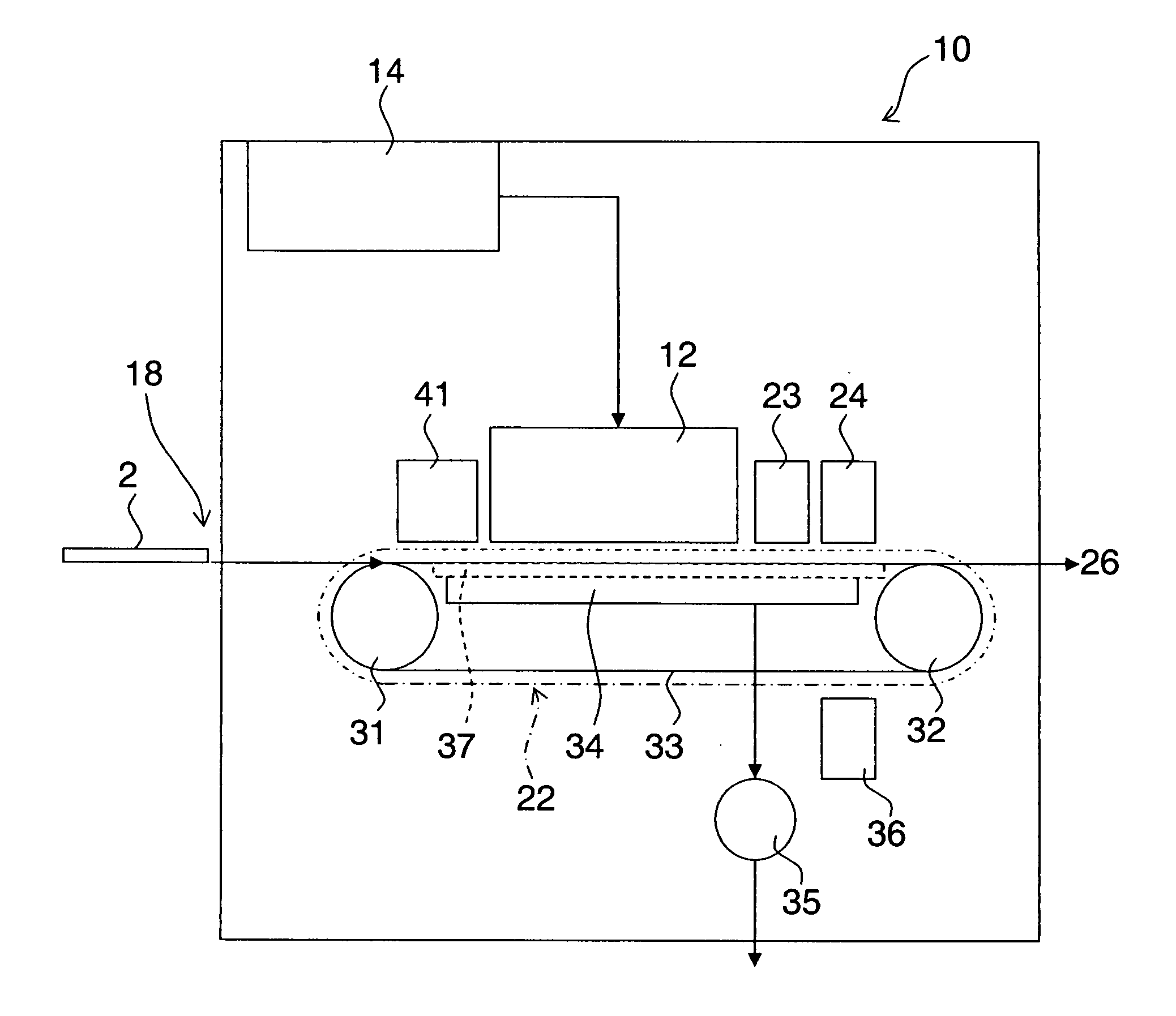
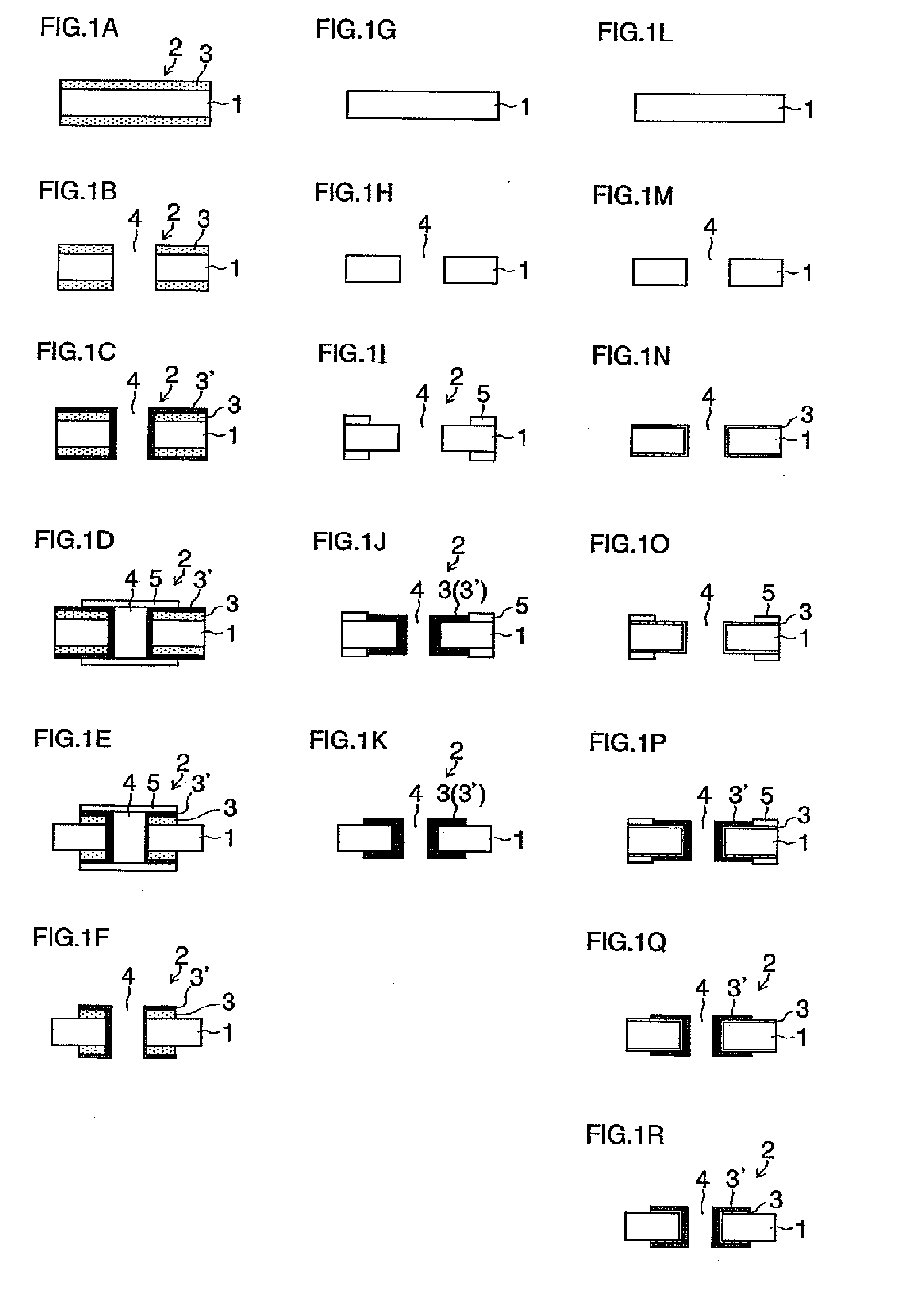
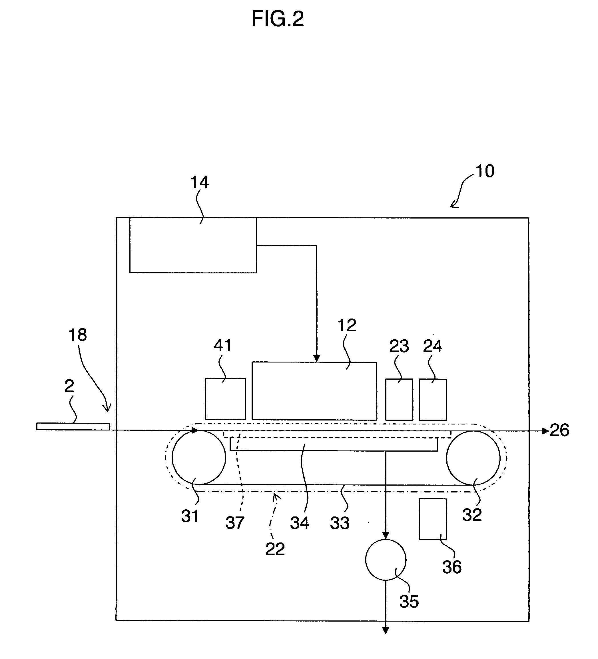
[0060]FIG. 2 is a diagram of the general composition of an inkjet (liquid jet) recording apparatus (liquid ejection apparatus) relating to an embodiment of the present invention. In the liquid-jet recording apparatus 10 according to the present embodiment of the invention, a resist layer 5 having a prescribed pattern as well as a prescribed thickness can be formed on the substrate 2 formed with a copper foil layer 3 (3′) (see FIGS. 1A and 1N) and the insulating substrate 1 (see FIG. 1I), by means of resist liquid.

[0061]The liquid-jet recording apparatus 10 shown in FIG. 2 comprises: a head 12 which ejects resist liquid; a resist liquid storing and accumulating unit 14 which stores the resist liquid to be supplied to the head 12; a supply unit 18 which supplies a substrate 2 (which may be a substrate formed with a copper foil layer or an insulating substrate on which a copper foil layer has not been formed); a ...

second embodiment

[0136]Next, a second embodiment of the present invention is described below. FIG. 9A is a plan diagram showing the nozzle arrangement in a head 120 relating to the second embodiment of the present invention. In the second embodiment described below, items which are the same as or similar to those in the first embodiment described above are labeled with the same or similar reference numerals and description thereof is omitted here.

[0137]The head 120 shown in FIG. 9A has the same nozzle arrangement as the head 12 having the arrangement shown in FIG. 4A, and it is a full line head in which a plurality of nozzles are aligned through a length of the substrate 2 corresponding to the main scanning direction, which is the breadthways direction of the substrate 2 (see FIG. 3), and ten nozzles (a number of nozzles corresponding to the maximum number of accumulated layers of resist liquid) are arranged equidistantly at an arrangement pitch of Pns in the sub-scanning direction, which is the dir...

modification example 1

[0164]Next, a modification example of the present invention is described below. FIG. 13 is a general schematic drawing of a liquid-jet recording apparatus 200 relating to the present modification example. Similarly to the liquid-jet recording apparatus 10 described above, the liquid-jet recording apparatus 200 shown in FIG. 13 forms a resist layer having a desired thickness (see FIGS. 1A to 1R) onto a substrate 2, by accumulating layers of resist liquid ejected onto the substrate 2. In the present modification example, the breadthways direction of the substrate 2 (in other words, the direction in which the head 202 moves with respect to the fixed substrate 2) is taken to be the main scanning direction, and the direction in which the substrate 2 is moved with respect to the head 202 is taken as the sub-scanning direction.

[0165]The print unit 204 comprises a carriage 208 which is movable reciprocally along two guide rails 206 extending in the main scanning direction, which is the brea...


PUM


Abstract

The liquid ejection apparatus has: a head having a nozzle group including a plurality of nozzles which are aligned in a first direction and performs ejection of resist liquid onto a wiring substrate; a scanning device which causes the head and the wiring substrate to move relatively in the first direction; an ejection control device which controls the ejection of the resist liquid from the head; and a scanning control device which controls the scanning device in such a manner that the head and the wiring substrate are relatively moved only once in the first direction, through a region of the wiring substrate which corresponds to one relative movement in the first direction of the wiring substrate and the scanning device, wherein the ejection control device controls the ejection of the resist liquid from the head to cause the resist liquid to be ejected onto a same position of the wiring substrate sequentially, at prescribed time intervals, from different nozzles of the nozzle group, to deposit the resist liquid ejected onto the same position of the wiring substrate sequentially from the different nozzles of the nozzle group, in such a manner that a resist pattern having a prescribed thickness and a prescribed pattern is formed on the wiring substrate.

Description

BACKGROUND OF THE INVENTION[0001]1. Field of the Invention[0002]The present invention relates to a liquid ejection apparatus and a resist pattern forming method, and more particularly, to resist patterning technology used when forming a wiring pattern on a printed wiring substrate.[0003]2. Description of the Related Art[0004]Photolithography is generally used as a method of manufacturing a print substrate. In photolithography, a resist layer is formed by using dry film resist or liquid resist on copper-clad laminate constituted by an insulating layer and a copper cladding layer made of copper foil, the resist layer is exposed in a pattern by being irradiated with ultraviolet light through a photo mask, and then development is carried out, thereby achieving patterning of a resist pattern. Thereupon, the copper foil which is not covered by the resist is removed by etching, thus obtaining a desired conductor pattern. The foregoing description relates to a subtractive type of photolitho...

Claims


Application Information

Patent Timeline
Patent Type & Authority Applications(United States)
IPC IPC(8): B41J29/38
CPCH01L21/6715H05K2203/013H05K3/0079
Inventor INOUE, SEIICHI
Owner FUJIFILM CORP
Why Eureka
Eureka Blog
Learn More