
Modular microwave processing system

a processing system and module technology, applied in microwave heating, electrical/magnetic/electromagnetic heating, electrical apparatus, etc., can solve the problems of time and laborious process of opening, securing the door, pumping and backfilling, venting, and opening the door

Inactive Publication Date: 2008-06-26
M S TECH
View PDF11 Cites 7 Cited by
  • Summary
  • Abstract
  • Description
  • Claims
  • Application Information

AI Technical Summary

Benefits of technology

The invention is a method for microwave processing that involves loading material into a portable metal chamber, securing the chamber, and applying microwave power to heat the material to a specific temperature for a set amount of time to create a solid mass. The method can also involve engaging a second process input device to control the heating process. The technical effect of this invention is a more efficient and controlled method for microwave processing that can be easily transported to different locations.

Problems solved by technology

It will be appreciated that the processes of opening the door, loading, securing the door, pumping and backfilling, venting, opening the door, and removing the workpiece and / or product are time and labor intensive.
All the time involved in these operations represents dead time during which the microwave equipment is idle.
Material may be lost, spilled, or diverted during loading and unloading operations in a conventional microwave processing cavity.
Furthermore, the processing of radioactive materials creates maintenance issues because contaminants from the processed materials may become dispersed throughout the interior of the waveguides, which are difficult to clean.
Also, if the microwave power supply is located in a hot cell, contamination zone, or similar radiation control area, the complexity and expense of maintaining the equipment increases considerably.

Method used


Image

  • Modular microwave processing system
  • Modular microwave processing system
  • Modular microwave processing system

Examples


example 1

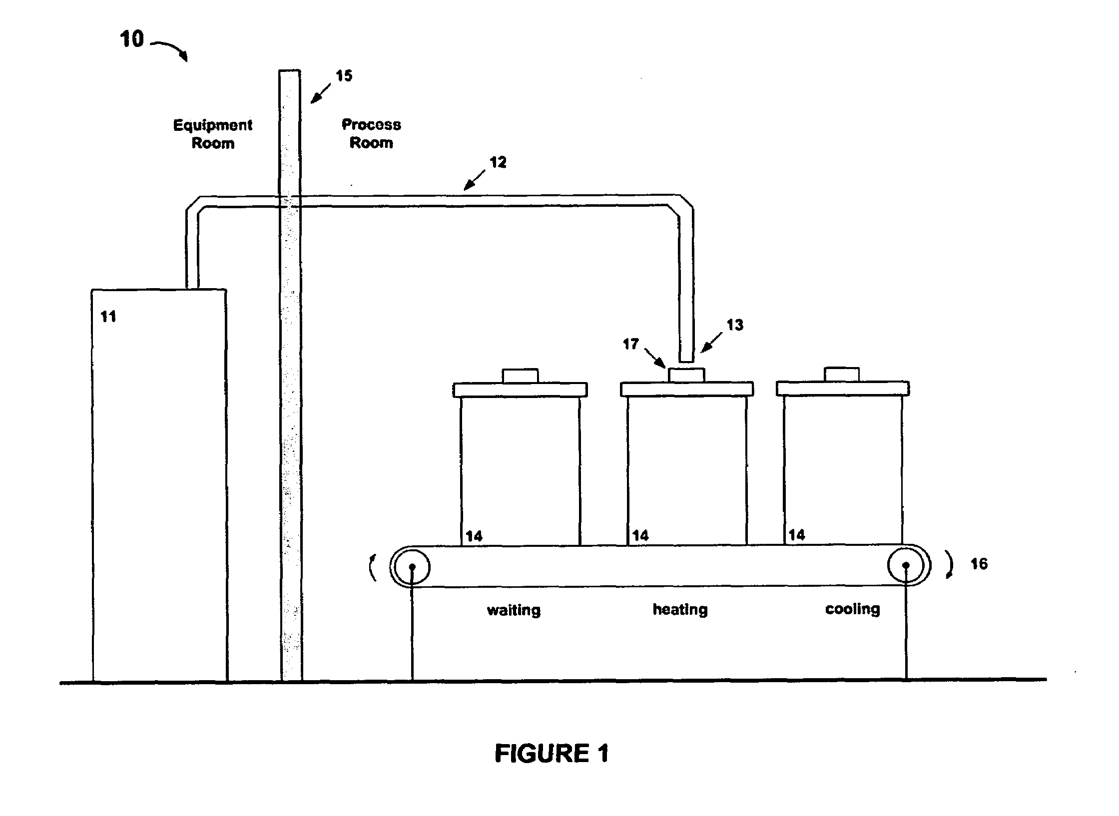
[0031]Referring to FIG. 1, the general layout of the invention is shown at 10. A microwave power source 11 provides microwave power via transmission line 12 to the output point 13. Modular process chambers 14, three of which are shown, have been pre-assembled and sealed.

[0032]Each chamber 14 has an interface device 17 configured to engage transmission line output point 13 whereby microwave power enters process chamber 14. Each process chamber 14 contains the workpiece to be heated, along with any desired fixture, molds, insulation, etc. The individual chambers 14 are transported, either individually (on casters, for instance) or on a conveyor (as shown schematically at 16), so that while one chamber is being actively heated, others may be waiting or cooling. Control of the atmosphere within each chamber 14, such as evacuation, backfilling, venting, etc., may be carried out during the waiting or cooling stages, thereby maximizing the time that microwave source 11 is utilized.

[0033]Th...

example 2

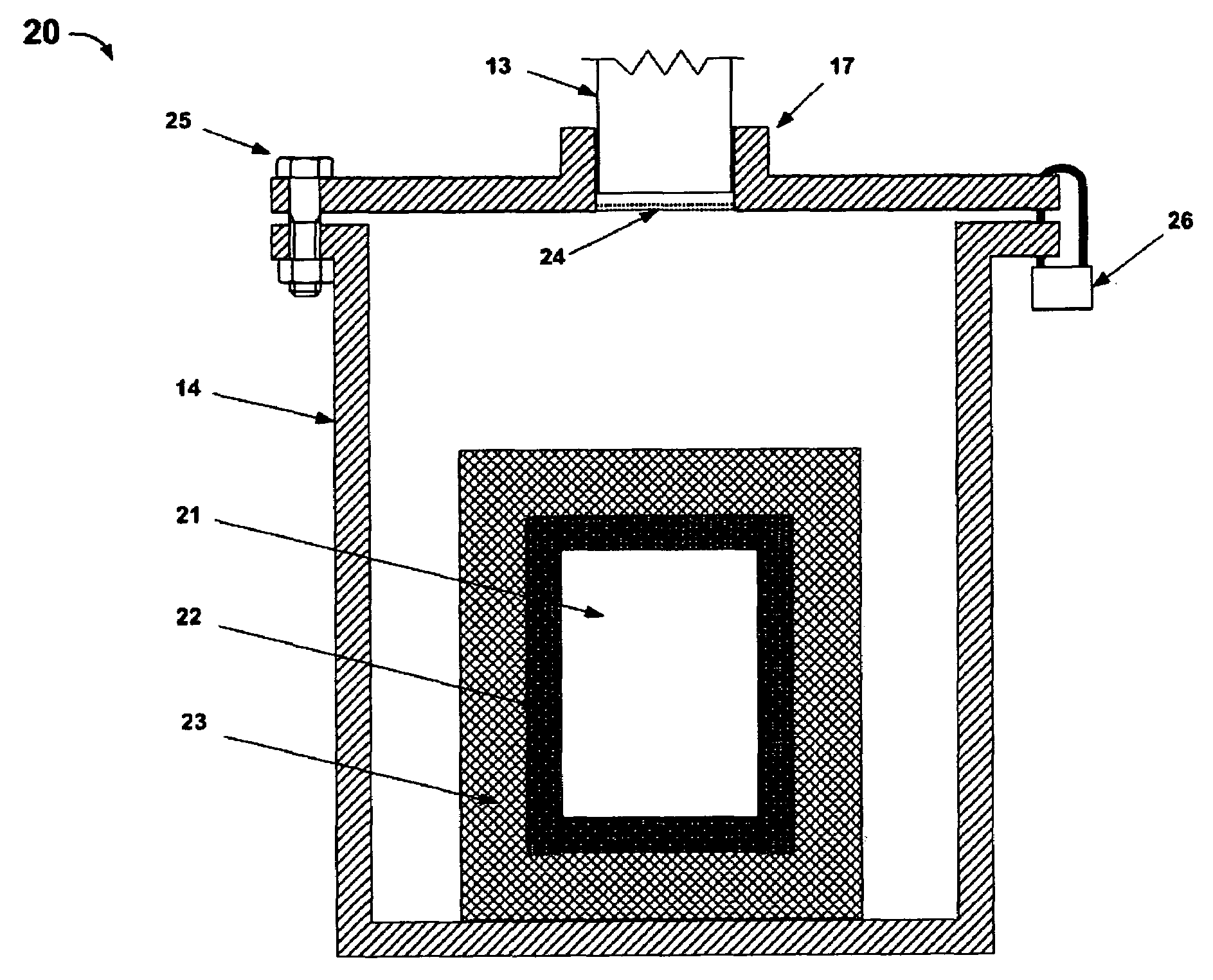
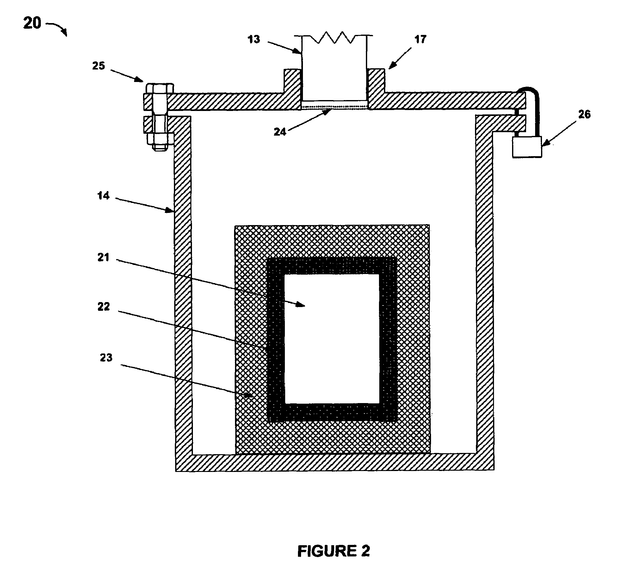
[0034]Referring to FIG. 2, an embodiment of the inventive process chamber 14 is shown in cross section at 20. Workpiece 21 in this case is contained in crucible 22, which in turn may optionally be surrounded by an insulating casket 23, hybrid heating materials, or other thermal management components, as are well known in the art of microwave processing. In this example, interface device 17 comprises a raised flange or boss to mechanically engage waveguide output point 13 and a dielectric window 24, through which microwave power enters chamber 14. Window 24 is preferably secured in place by brazing. The top of chamber 14 is secured to the body by bolts 25, lock 26, or other conventional means. The interface device may optionally contain additional features (not shown) intended to suppress leakage of microwave power from the area where the waveguide meets the interface device. These features may include gaskets, metal finger stock, steel braid, or other structures as are familiar to m...

example 3

[0035]Illustrated at 30 in FIG. 3, an embodiment of the microwave transmission line of the present invention is shown in the expanded view of the top of chamber 14. The microwave waveguide is inserted and sealed using electromagnetic gaskets 31 or microwave chokes as are well known in the art of microwave processing. A mechanical switch 34 is located proximate to the waveguide, and this switch is part of a safety interlock system that prevents the microwave power feed from being energized unless the chamber 14 is securely engaged at the end of the feed.

[0036]Those skilled in the art of microwave system design will appreciate that microwave power may be transmitted via a waveguide such as that shown in FIG. 3 or may alternatively be transmitted via a coaxial transmission line. In the latter case, the interface device will comprise a coaxial feedthrough with an antenna structure or feed horn integral with chamber 14, whereby microwave power from a coaxial feed line will be effectively...


PUM


Abstract

A modular microwave processing system includes a microwave source, a transmission line, and a detachable processing cavity or chamber. The chamber is adapted to maintain a controlled atmosphere surrounding a workpiece, and further contains an interface to engage the microwave transmission line so that power for heating the workpiece is introduced through the interface. The system is particularly suited for remote operation and for processing hazardous or accountable materials. It may also be adapted for operation in a hot cell or other controlled area while locating the microwave power source outside of the controlled area for ease of maintenance. Material to be treated may be loaded into the chamber and heated to fuse the material into a substantially solid mass, and then sent for disposal using the chamber itself as a robust permanent container. Material being treated may also be acted upon by other process input devices configured to be compatible with the detachable processing chamber.

Description

CROSS-REFERENCE TO RELATED APPLICATION[0001]This application is a division of U.S. patent application Ser. No. 11 / 412,041 filed by Kenneth R. Givens on Apr. 26, 2006, the entire disclosure of which is incorporated herein by reference.BACKGROUND OF THE INVENTION[0002]1. Field of the Invention[0003]The invention pertains to apparatus and methods for microwave processing of materials. More particularly, the invention pertains to apparatus and methods for heating materials in a modular chamber adapted to receive power from a remote microwave source.[0004]2. Description of Related Art[0005]Microwaves have been commonly used in many industrial heating processes. Well-known examples include cooking, rubber processing, ceramic sintering, and others. It is standard practice in these systems to use a microwave power source that delivers microwave power to a closed applicator cavity via one or more waveguides, which typically are rigidly connected to a wall of the cavity. For continuous proces...

Claims


Application Information

Patent Timeline
Patent Type & Authority Applications(United States)
IPC IPC(8): H05B6/64
CPCH05B6/6402H05B6/78H05B6/745H05B6/70
Inventor GIVENS, KENNETH R.
Owner M S TECH
Learn More