
Heat Exchanger

a technology of heat exchanger and heat exchanger plate, which is applied in the direction of light and heating apparatus, machines/engines, laminated elements, etc., can solve the problems of increasing the number of brazing portions on the parts, increasing the number of brazing portions, and prone to leakage at the brazing portion, etc., to eliminate the gap, reduce the number of leakages, and reduce the number of cracks

Inactive Publication Date: 2008-06-12
T RAD CO LTD
View PDF32 Cites 25 Cited by
  • Summary
  • Abstract
  • Description
  • Claims
  • Application Information

AI Technical Summary

Benefits of technology

The design reduces the number of parts, simplifies assembly, increases brazing reliability, prevents fluid leakage, and enhances heat exchange performance by eliminating gaps and promoting even fluid distribution.

Problems solved by technology

In the former heat exchanger such as the EGR cooler, the number of parts is large, which makes assembling cumbersome and increases the number of brazing portions on the parts, and there is a problem that a leakage tends to occur at the brazing portion.
In this type of heat exchanger, there is a problem that a gap tends to occur at a brazed portion between the root of each comb tooth and the side face of the core body as well as between the tip end of each comb tooth and each groove bottom, from which leakage of a fluid easily occurs.
Along with that, a crack is easily generated at a brazed portion particularly at the root portion of each comb tooth by a heat stress or the like due to use of the heat exchanger.

Method used


Image

  • Heat Exchanger
  • Heat Exchanger
  • Heat Exchanger

Examples


Embodiment Construction

[0034]Next, embodiments of the present invention will be described based on the attached drawings.

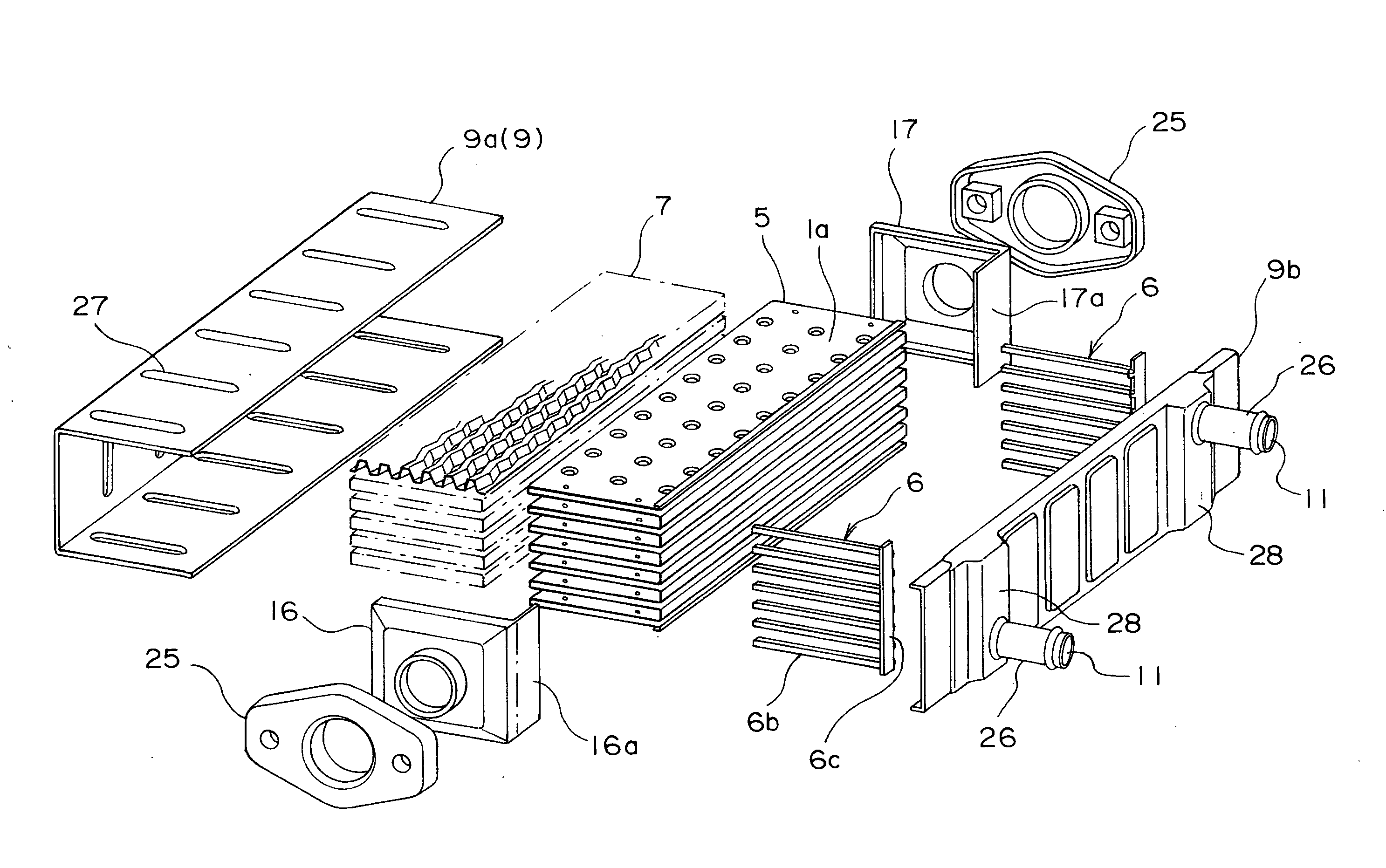
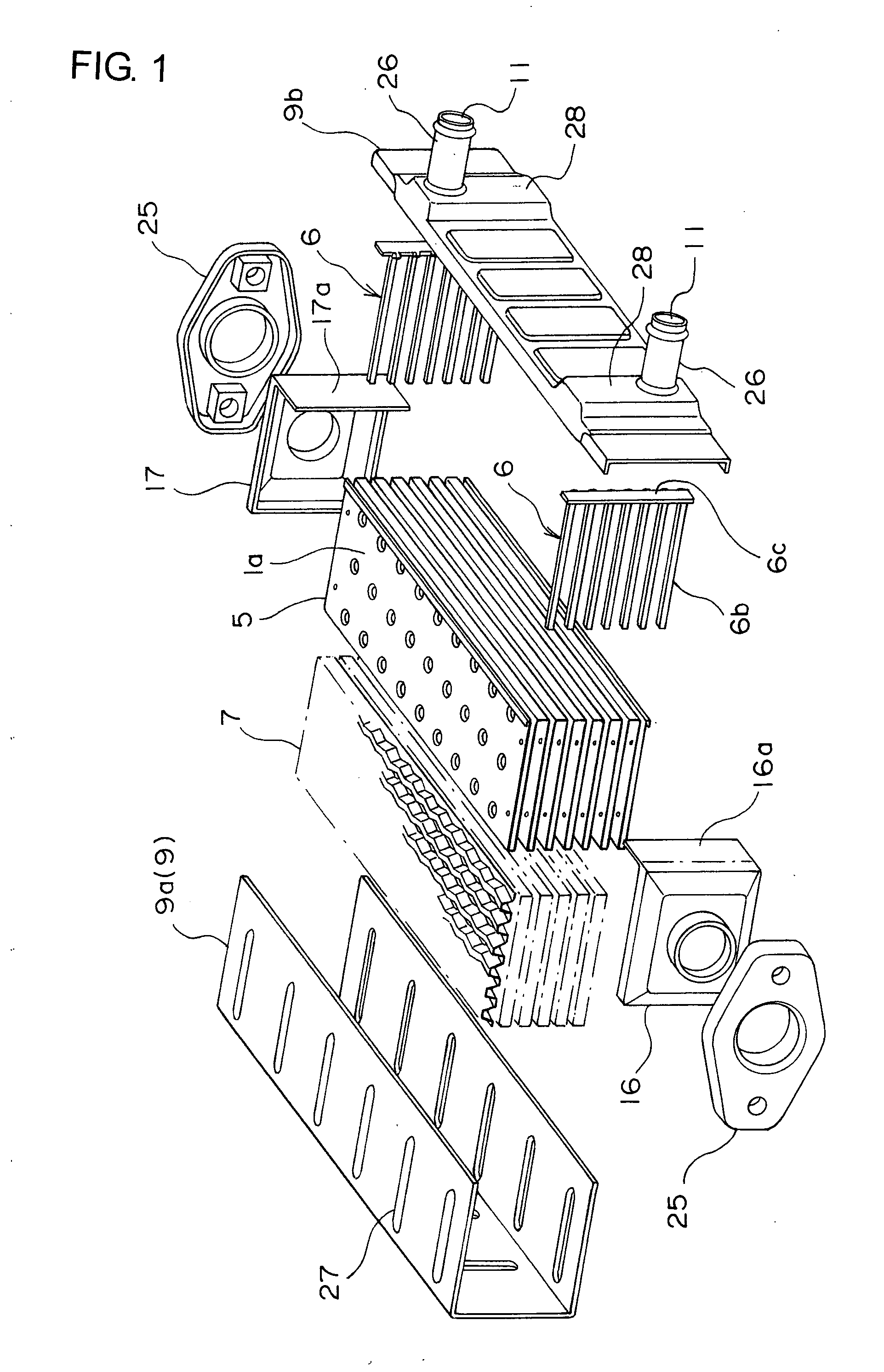
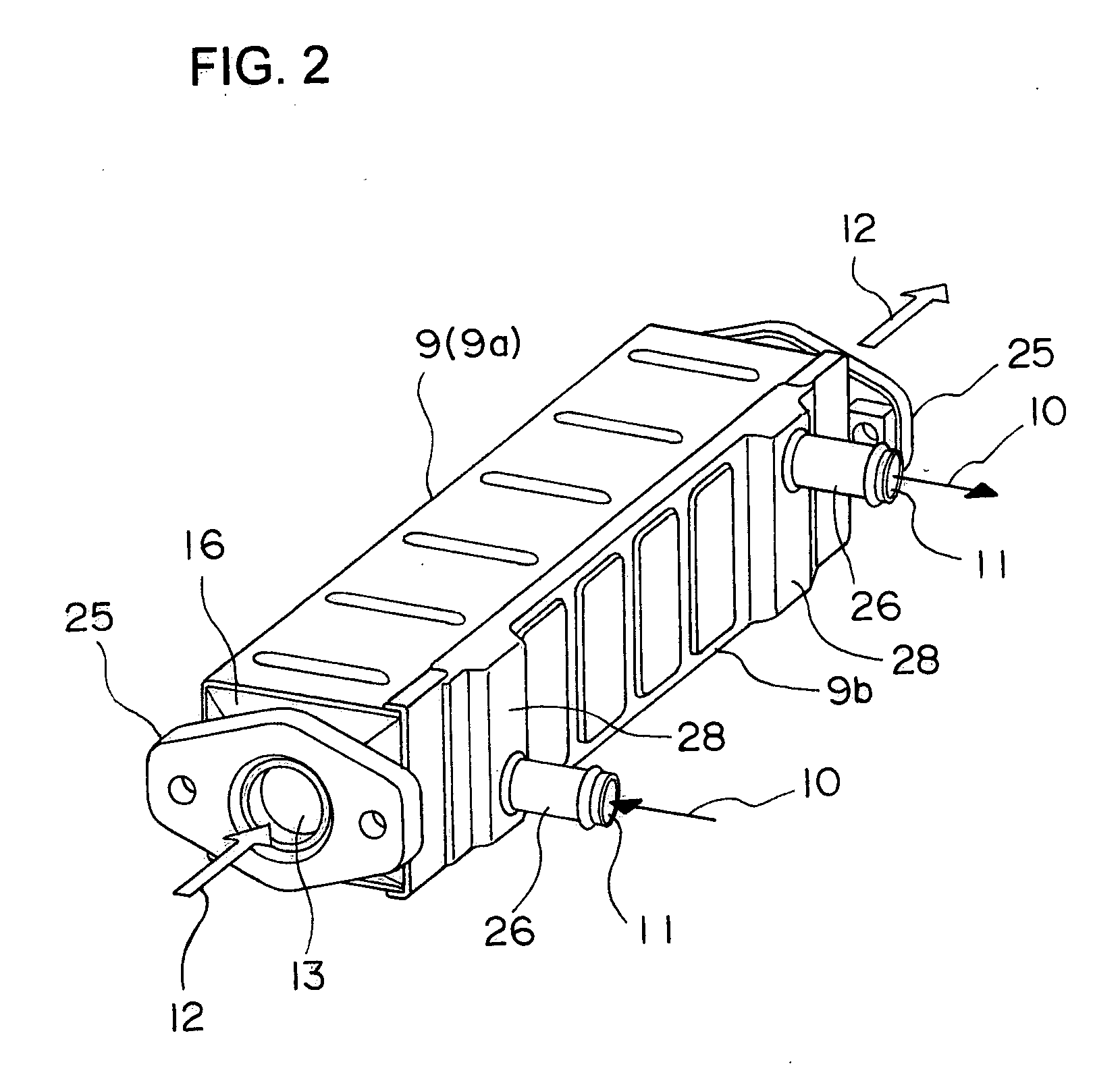
[0035]FIG. 1 is an exploded perspective view of a heat exchanger of the present invention, FIG. 2 shows its assembled state and FIG. 3 is an explanatory view of an assembly of a core body 5 and a comb-state member 6. Also, FIG. 4 is a perspective view of the comb-state member, FIG. 5 is a partially cutaway enlarged perspective view illustrating the assembled state, and FIG. 6 is a perspective view of the assembled state.

[0036]Moreover, FIG. 9 is a cross sectional view of the heat exchanger and FIG. 10 is an enlarged view of IX part of FIG. 9.

[0037]This heat exchanger has a core body 5, a large number of fins 7, a casing 9, a pair of headers 16, 17, and the pair of comb-state members 6.

[0038]The core body 5 is formed by turning up and bending a strip-shaped metal plate in a fanfold manner as shown in FIG. 3 so that turned-up end edges 1, 2 are formed alternately at one end and the other ...


PUM


Abstract

In a heat exchanger in which the number of parts is small, assembling is easy, bonded portions of each part are fewer and reliability of brazing is improved, a core body is constituted by turning up and bending a strip-shaped metal plate in a fanfold manner, and first flow passages and second flow passages are formed alternately in the thickness direction. Both ends of each of the first flow passages are blocked by each come tooth of a pair of comb-state members, and a fin is set within the second flow passages so as to constitute a core. And in the heat exchanger in which a cylindrical casing is fitted with the outer periphery of the core body, the comb-state member has its tooth base crossing perpendicularly with each of the comb tooth and a root of each comb tooth bent in the L-shape along the tooth base, the plane of the tooth base is brought into contact with a turned-up end edge, and each connection portion between the comb-state member and the core body is integrally brazed / fixed.

Description

BACKGROUND OF THE INVENTION[0001]The present invention relates to a heat exchanger in a simple structure which can be applied to a heat exchanger (EGR cooler) used in an exhaust gas recirculation apparatus in an automobile and other heat exchangers, in which a core body formed by bending a strip-shaped metal plate in a fanfold manner, and having flat first flow passages and second flow passages alternately in the thickness direction of the metal plate, each of the first flow passages of the core body being blocked by each tooth of a pair of comb-state members at both end positions.[0002]A conventional EGR cooler is made of an assembly of a large number of flat tubes or a large number of plates, a large number of fins, a casing and a header, in which cooling water is made to communicate through the casing side and an exhaust gas is made to communicate inside each of the flat tubes or the like as proposed in the invention described in Japanese Patent Application Laid-Open No. 5-18634....

Claims


Application Information

Patent Timeline
Patent Type & Authority Applications(United States)
IPC IPC(8): F28D7/06
CPCF02M25/0737F28D9/0025Y02T10/121F28F9/026F28F2220/00F28F3/025F28F21/083F02M26/32
Inventor NAKAMURA, YOICHI
Owner T RAD CO LTD
Learn More