
Reforming and Hydrogen Purification System

a hydrogen purification system and reformer technology, applied in the field of steam reformers, can solve the problems of low power and low cost air supply for hydrogen rich fuel processing, and achieve the effects of low power, minimal pressure drop, and efficient heating of the reformer

Inactive Publication Date: 2008-06-12
GENESIS FUEL TECH INC
View PDF62 Cites 11 Cited by
  • Summary
  • Abstract
  • Description
  • Claims
  • Application Information

AI Technical Summary

Benefits of technology

The present invention is a hydrogen purification reformer that can be constructed as a compact unit with efficient heating from a burner. The burner gas has a minimal pressure drop in the system, resulting in a low power and low cost air supply for processing of the hydrogen rich fuel. The reformer system includes a catalyst unit or bed which is operable upon heating to establish an endothermic reaction on the feedstock to produce hydrogen. A hydrogen collector is located to collect the purified hydrogen, which can be a hydrogen selective permeable membrane unit. The system also includes a pressure vessel containing a closed hydrogen selective permeable membrane core unit surrounded by a catalyst bed or unit. The hydrogen rich feedstock passes through the heated catalyst unit, producing hydrogen. The hydrogen then passes through the hydrogen selective permeable membrane core unit and exits the pressure vessel. The heating unit is preferably a catalytic burner which is fueled by the raffinate exiting the pressure vessel. The pressure vessel is also preferably formed with a hydrogen collection system including one or more collection structures.

Problems solved by technology

The burner gas has a minimal pressure drop in the system which results in a low power and low cost air supply for processing of the hydrogen rich fuel.

Method used


Image

  • Reforming and Hydrogen Purification System
  • Reforming and Hydrogen Purification System
  • Reforming and Hydrogen Purification System

Examples


Embodiment Construction

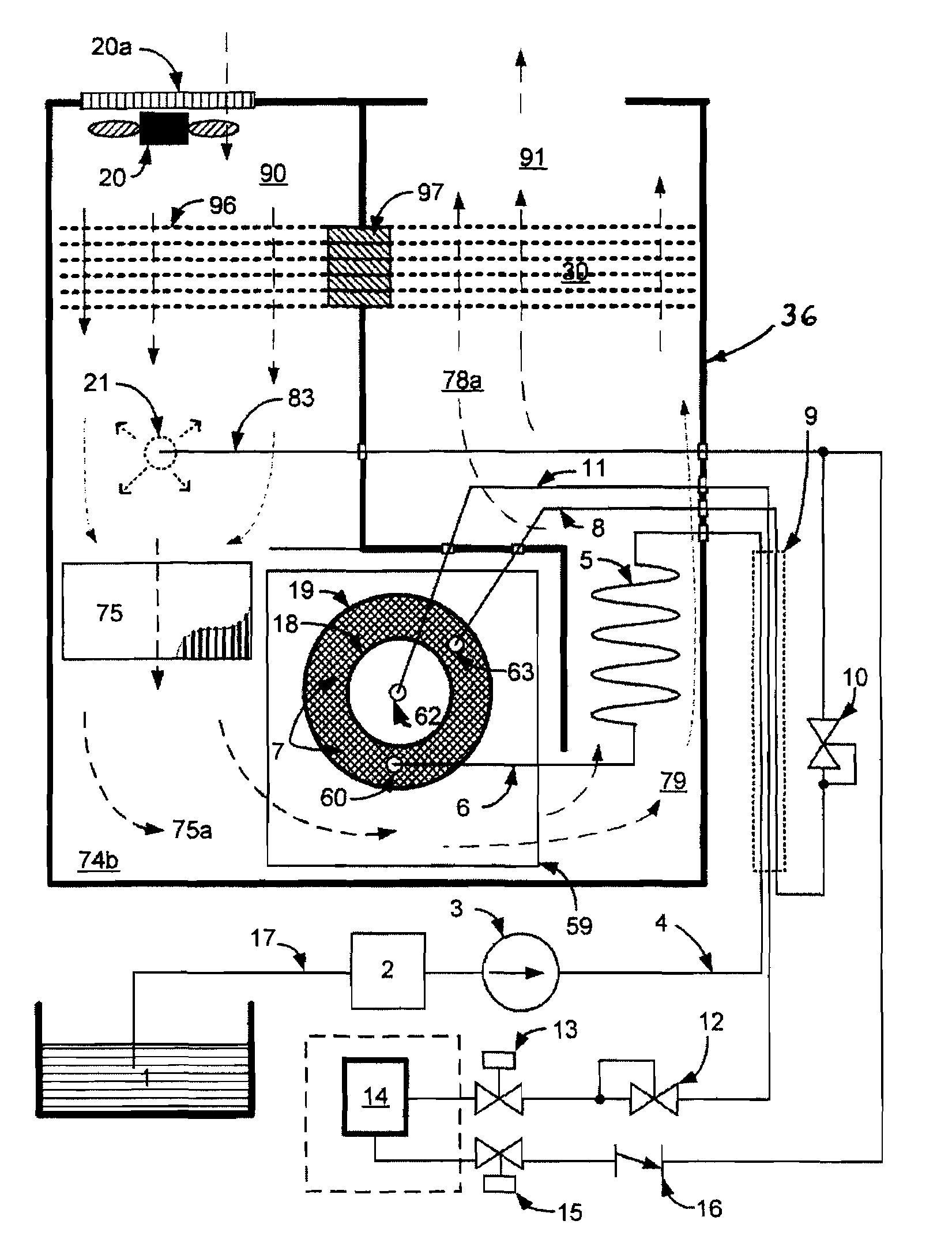
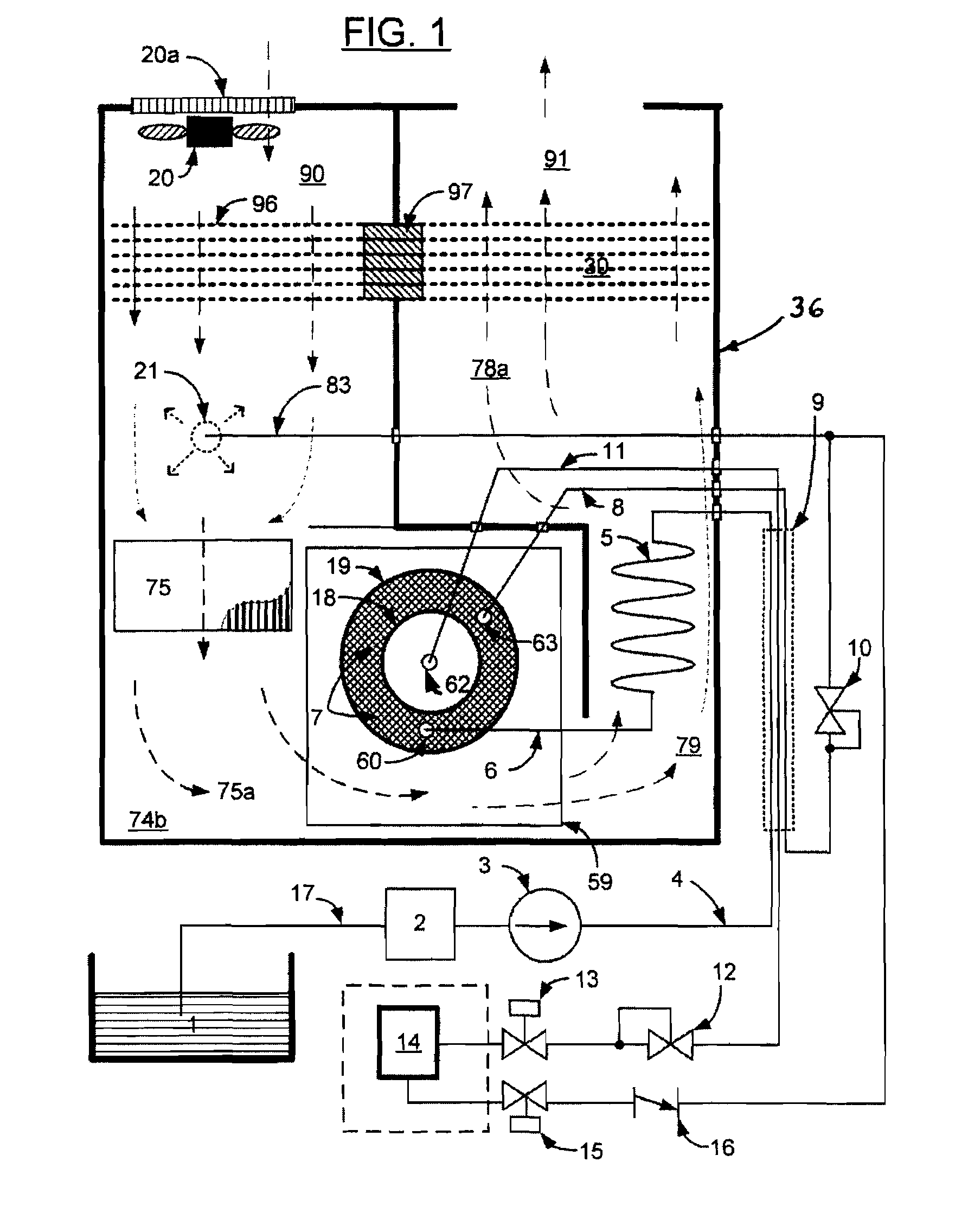
[0050]FIG. 1 is a simplified illustration of a system for generating purified hydrogen from a hydrogen rich fuel source 1 for consumption by device 14, which may, for example, be a fuel cell used for supplying electrical power to a load. The illustrated embodiment of FIG. 1 includes a unique hydrogen purifier 18 within a suitable support such as outer housing 36, in combination with the associated components.

[0051]The system of FIG. 1 includes a steam reformer having a reformer pressure vessel unit 19 which is operable to process fuel / water feedstock from a source 1. Although a common pump for the fuel and water is illustrated for the case where the fuel and water are miscible as a pre-mixed feedstock, it is understood that more than one pump may be used for the fuel and water, respectively, along with any needed flow and pressure monitoring means, with the fuel and water streams meeting together prior to arriving at the catalyst filled chamber 7. The pressure vessel unit 19 contain...


PUM

PropertyMeasurementUnit
light-off temperatureaaaaaaaaaa
thermally conductiveaaaaaaaaaa

Abstract

A reforming and hydrogen purification system operating with minimal pressure drop for producing free hydrogen from different hydrogen rich fuels includes a hydrogen reforming catalyst bed in a vessel in communication with a core unit containing a hydrogen permeable selective membrane. The vessel is located within an insulated enclosure which forms an air inlet passageway and an exhaust passageway on opposite sides of the vessel. Air and raffinate pass through a burner within the air inlet passageway, providing a heated flue gas to heat the catalyst to the reaction temperature needed to generate free hydrogen from the feedstock. The burner flue gas flows laterally over and along the length of the bed between the input and output ends of the bed. Hydrogen is recovered from the core for use by a hydrogen-consuming device such as a fuel cell. The remaining unrecovered hydrogen in the reformed gases is contained in raffinate and is used to supply process heat via the burner. The exhaust flue gas and the inlet air supply pass through a recuperator in which the inlet air is heated from the hot exhaust gas. The feedstock input line is also coupled to the raffinate line and the hydrogen recovery line to preheat the feedstock prior to entry into the catalyst bed.

Description

BACKGROUND OF THE INVENTION[0001]The present invention is directed to a steam reformer for producing purified hydrogen including purified hydrogen for fuel cells.[0002]Purified hydrogen is an important commodity in semiconductor, metallurgical, and chemical processing. It is also highly useful as a source of fuel for fuel cells, which can produce electrical power from hydrogen. There are a variety of means for producing purified hydrogen. Hydrogen can be liberated from hydrogen-containing compounds such as alcohol by reforming with steam at elevated temperatures over a catalyst bed. Since this reaction is endothermic, the heat can be supplied from an external burner, or the heat can be supplied in-situ by mixing some oxygen and partially burning some of the fuel. The former process is generally called steam reforming; when air or oxygen is mixed with the fuel to supply heat the process is referred to as autothermal or partial oxidation reforming. Once the reforming process has been ...

Claims


Application Information

Patent Timeline
Patent Type & Authority Applications(United States)
IPC IPC(8): B01J7/00C01B3/38C01B3/50
CPCC01B3/384C01B3/501C01B2203/0811C01B2203/0405C01B2203/041C01B2203/0233Y02P20/129Y02E60/50
Inventor DEVRIES, PETER DAVID
Owner GENESIS FUEL TECH INC
Learn More