
Apparatus, system, and method for maximizing ultrafine meltblown fiber attenuation

a technology of attenuation and ultra-fine fiber, applied in the field of meltblown fiber manufacture, can solve the problems of many manufacturing problems, unstable attenuation force, and violent behavior, and achieve the effect of maximizing the attenuation of ultra-fine meltblown fiber

Inactive Publication Date: 2008-05-29
CUMMINS FILTRATION IP INC
View PDF5 Cites 4 Cited by
  • Summary
  • Abstract
  • Description
  • Claims
  • Application Information

AI Technical Summary

Benefits of technology

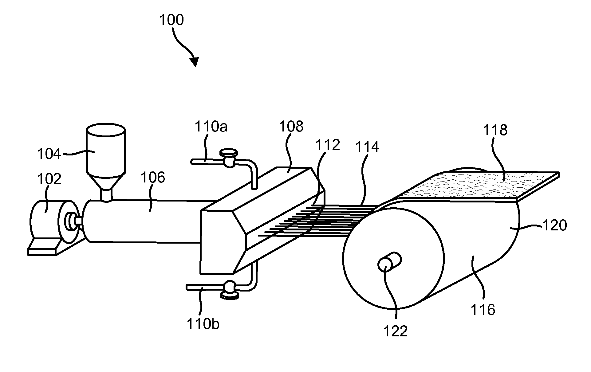
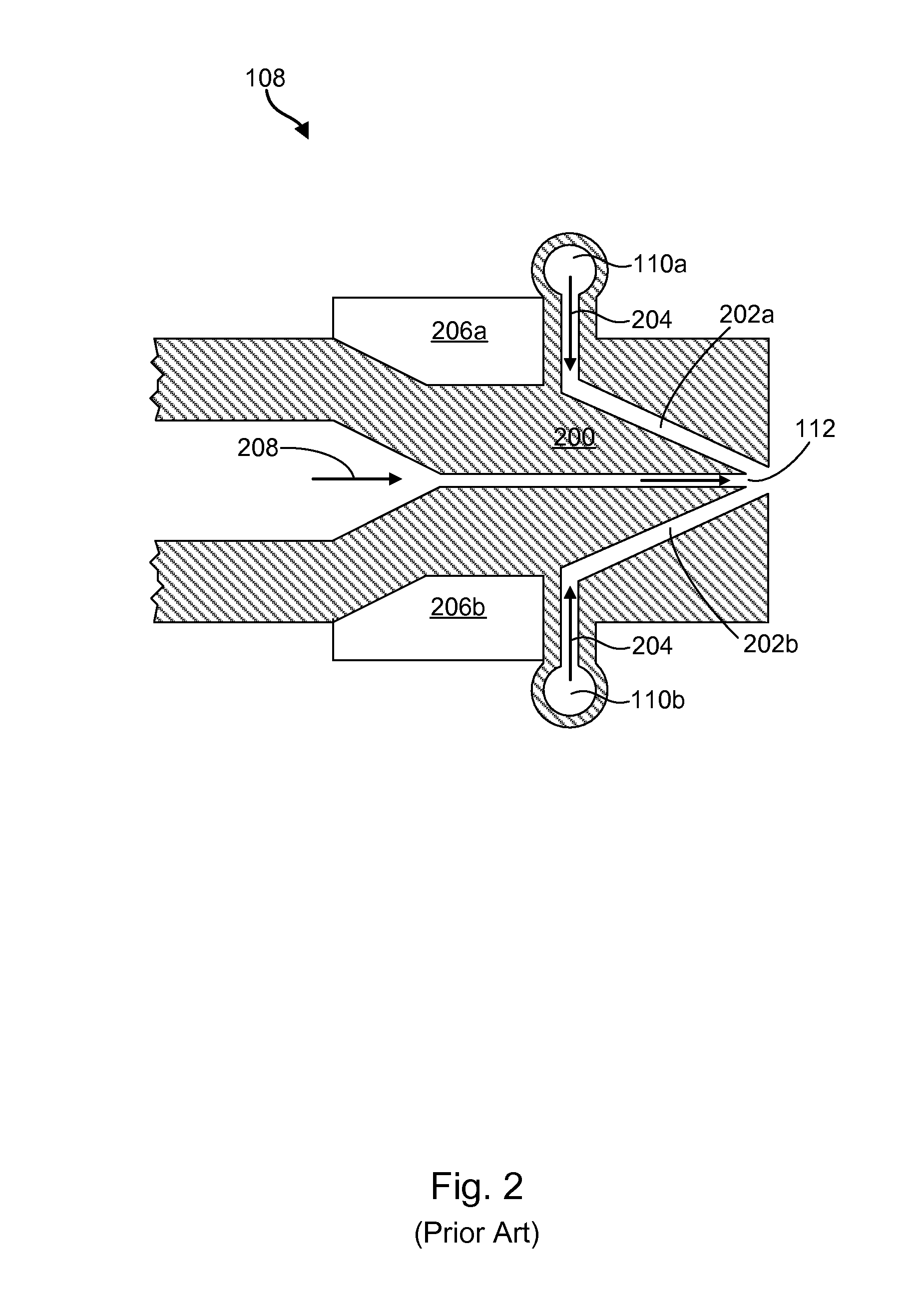
[0010]A nozzle apparatus to maximize ultrafine meltblown fiber attenuation in accordance with certain embodiments of the present invention includes a polymer streaming channel having an inlet and an outlet. The polymer streaming channel may direct a polymer therethrough in a direction from the inlet to the outlet. In some embodiments, the polymer includes a block co-polymer having a low viscosity and an increased melt strength. In other embodiments, the polymer includes a polyester, a polyamide, polyphenylene sulfide, and / or polypropylene.
[0012]A restricted throat area may restrict gas flow where the gas delivery channels converge such that the gas reaches supersonic speeds in the fiber attenuation zone. A bounded expansion area extending from the restricted throat area may stabilize the supersonic gas flow in the fiber attenuation zone. In certain embodiments, the shape and / or dimensions of the restricted throat area and bounded expansion area determines where a downstream shock may be positioned. The downstream shock may be positioned, for example, within the bounded expansion area, at an edge of the bounded expansion area, or beyond the bounded expansion area.
[0015]A method of the present invention is also presented for maximizing ultrafine meltblown fiber attenuation. In one embodiment, the method includes streaming a polymer through a channel, directing a flow of gas through at least one gas delivery channel, restricting the flow of gas, and directing the gas through a bounded expansion area. In some embodiments, the method may further include selecting a polymer having a low viscosity and a high melt strength, such as a block co-polymer.

Problems solved by technology

Although supersonic air velocities have been attempted in an effort to reduce fiber diameters, such velocities create violent, unstable attenuation forces.
These forces cause the creation of “fly,” a defect consisting of short segments of very fine microfibers that break off from the continuous strand of molten polymer and are not collected by the collecting screen during laydown.
While fly may not directly affect the quality of the web, it causes many other manufacturing problems by contaminating the surrounding production environment.
In addition, fly may cause web non-uniformity by intermittently collecting on the web in “clumps” of agglomerated free-floating fibers.
Other existing sub-micron polymer fiber manufacturing technologies, such as solvent electrospinning methods, are very expensive, dangerous, and low-volume oriented.

Method used


Image

  • Apparatus, system, and method for maximizing ultrafine meltblown fiber attenuation
  • Apparatus, system, and method for maximizing ultrafine meltblown fiber attenuation
  • Apparatus, system, and method for maximizing ultrafine meltblown fiber attenuation

Examples


Embodiment Construction

[0028]Reference throughout this specification to “one embodiment,”“an embodiment,” or similar language means that a particular feature, structure, or characteristic described in connection with the embodiment is included in at least one embodiment of the present invention. Thus, appearances of the phrases “in one embodiment,”“in an embodiment,” and similar language throughout this specification may, but do not necessarily, all refer to the same embodiment.

[0029]Furthermore, the described features, structures, or characteristics of the invention may be combined in any suitable manner in one or more embodiments. In the following description, numerous specific details are disclosed to provide a thorough understanding of embodiments of the present invention. One skilled in the relevant art will recognize, however, that the invention may be practiced without one or more of the specific details, or with other methods, components, materials, and so forth. In other instances, well-known str...


PUM

PropertyMeasurementUnit
Pressureaaaaaaaaaa
Pressureaaaaaaaaaa
Viscosityaaaaaaaaaa

Abstract

An apparatus, system and method to maximize ultrafine meltblown fiber attenuation. The nozzle apparatus includes a polymer streaming channel, at least one gas delivery channel, a restricted throat area, and a bounded expansion area. In some embodiments, the nozzle comprises a two-dimensional converging-diverging Laval nozzle geometry. The gas delivery channels may provide the gas under a pressure exceeding critical pressure, such that the gas achieves supersonic speeds at the restricted throat area. The bounded expansion area may stabilize such supersonic speeds, thus maximizing ultrafine meltblown fiber attenuation while minimizing the formation of fly and other defects.

Description

BACKGROUND OF THE INVENTION[0001]1. Field of the Invention[0002]This invention relates to meltblown fiber manufacture, and more particularly relates to systems and methods for maximizing ultrafine meltblown fiber attenuation.[0003]2. Description of the Related Art[0004]Meltblowing processes are highly effective to produce super-fine fibers on the micron or sub-micron scale. In general, meltblowing processes involve heating and extruding a thermoplastic fiber-forming polymer through tiny orifices in a meltblown die head. The molten polymer is then subjected to convergent streams of high velocity gas, such as air, to rapidly attenuate the polymer into microfibers having a diameter less than the diameter of the orifices in the die head. The gas has a temperature higher than or equal to the temperature of the molten polymer and is blown against the molten polymer in the direction of flow. In this manner, the high velocity gas also moves the resulting microfibers toward a collecting scre...

Claims


Application Information

Patent Timeline
IPC IPC(8): B29C39/14
CPCD01D4/025
Inventor HERMAN, PETER K.STUART, JAMES O.VELU, YOGESHWAR K.
Owner CUMMINS FILTRATION IP INC
Learn More