
Hermetically sealed compressor and method of manufacturing the same

a technology of hermetically sealed compressors and compressors, which is applied in the direction of machines/engines, rotary/oscillating piston pump components, liquid fuel engines, etc., can solve the problems of reducing the cooling efficiency of hermetically sealed rotary compressors, and achieve the effect of enhancing sealing performance and cooling efficiency

Active Publication Date: 2008-05-15
SANYO ELECTRIC CO LTD
View PDF9 Cites 20 Cited by
  • Summary
  • Abstract
  • Description
  • Claims
  • Application Information

AI Technical Summary

Benefits of technology

The present invention provides a hermetically sealed compressor with enhanced sealing performance between the roller and cylinder, resulting in improved cooling efficiency. This is achieved by injecting oil into the compression chamber when the refrigerant is sucked into the compression chamber in the cylinder. The compressor includes an oil supply device for supplying oil to the rubbing place between the electrically-driven element and the rotary compressing element, and an oil path for leading the oil to the compression chamber. The compressor can be equipped with a primary and secondary bearing member to support the cylinder. The oil path can be formed within the contact face between the cylinder and the bearing member or the cylinder and the plate-shaped member sandwiching the cylinder. The size of the oil path can be determined based on the displacement volume of the compression chamber. The method of manufacturing the compressor includes forming a through hole in the bearing member and an oil path in the container.

Problems solved by technology

However, the conventional hermetically sealed rotary compressor has a problem that the sealing performance of the crescent-shaped space is not sufficient, resulting in reduction of the cooling efficiency of the hermetically sealed rotary compressor.

Method used


Image

  • Hermetically sealed compressor and method of manufacturing the same
  • Hermetically sealed compressor and method of manufacturing the same
  • Hermetically sealed compressor and method of manufacturing the same

Examples


first embodiment

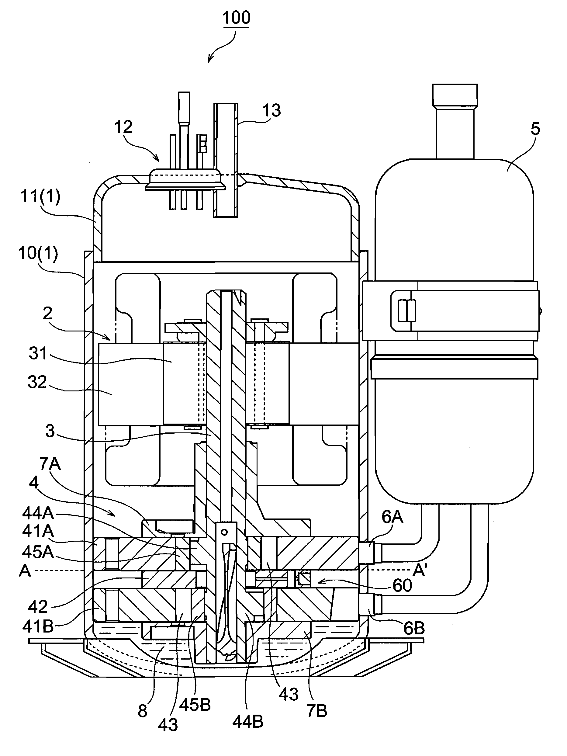
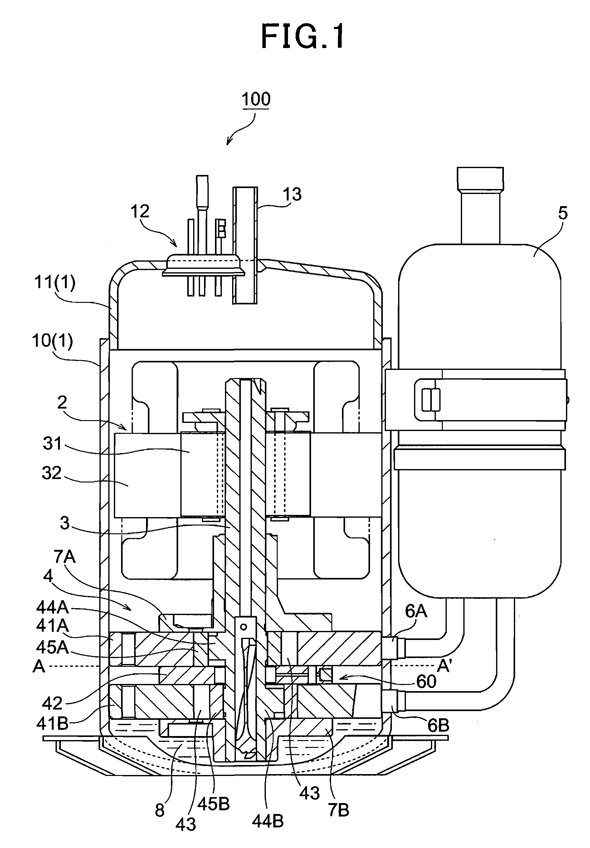
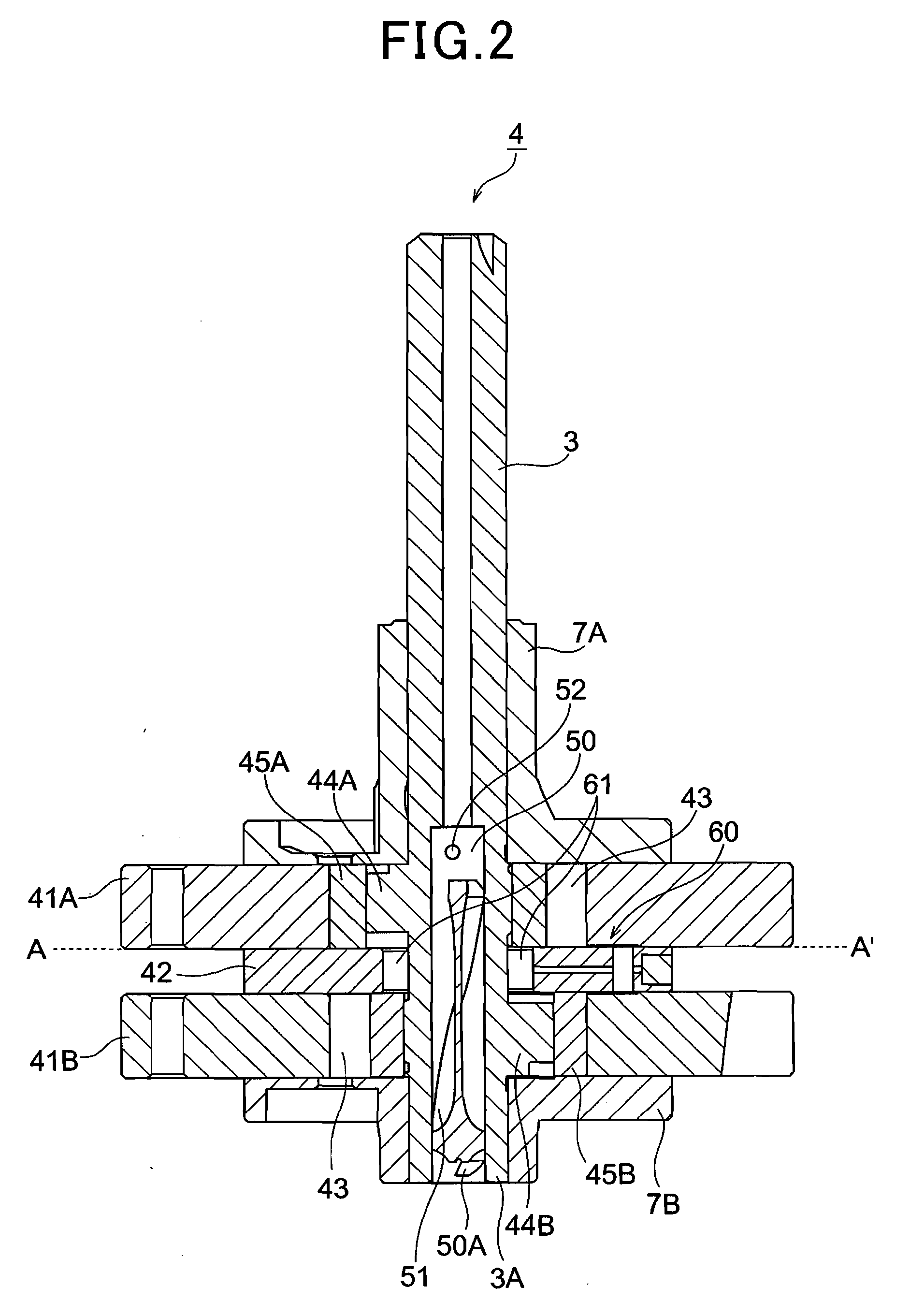
[0044]FIG. 1 is a longitudinally-sectional view showing a hermetically sealed rotary compressor according to a first embodiment of the present invention, and FIG. 2 is an enlarged longitudinally-sectional view of a rotary compressing element. The hermetically sealed rotary compressor 100 constructs a refrigerating unit by connecting a condenser for refrigerant and an evaporator for refrigerant through a pipe. As shown in FIG. 1, the hermetically sealed rotary compressor 100 has a hermetically sealed container 1, an electrically-driven element 2 accommodated at the upper side of the hermetically sealed container 1, and a rotary compressing element 4 accommodated at the lower side of the hermetically sealed container 1. The rotary compressing element 4 is driven by a crank shaft 3 of the electrically-driven element 2 to compress refrigerant.

[0045] The hermetically sealed container 1 is equipped with a cylindrical shell portion 10, and an end cap 11 fixed to the shell portion 10 by ar...

second embodiment

[0075] Next, a second embodiment according to the present invention will be described.

[0076]FIG. 6 is a longitudinally-sectional view showing a hermetically sealed rotary compressor 100A according to a second embodiment of the present invention, and FIG. 7 is an enlarged longitudinally-sectional view showing a rotary compressing element.

[0077] As shown in FIGS. 6 and 7, the hermetically sealed rotary compressor 100A is greatly different in the construction of the rotary compressing element from the first embodiment. The construction of the other parts are substantially the same as the first embodiment, and thus the rotary compressing element of the second embodiment will be described in detail in the following description. The same elements as the first embodiment are represented by the same reference numerals, and the description thereof is omitted.

[0078] The rotary compressing element 4A is constructed so as to have one cylinder 41 unlike the rotary compressing element 4 of the...

third embodiment

[0106] Next, a third embodiment according to the present invention will be described.

[0107]FIG. 12 is a longitudinally-sectional view showing a hermetically sealed rotary compressor 100B according to a third embodiment of the present invention, and FIG. 13 is an enlarged longitudinally-sectional view. As shown in FIGS. 12 and 13, in the hermetically sealed rotary compressor 100B of this embodiment, a rotary compressing element 4B is equipped with one cylinder 41 as in the case of the second embodiment, and the basic construction thereof is similar to the second embodiment. Therefore, the same elements as the second embodiment are represented by the same reference numerals, and the description thereof is omitted.

[0108] In order to enhance the refrigerant compression efficiency, the hermetically sealed rotary compressor 100B is designed so that the oil 8 is injected into the compression chamber 43 when the refrigerant is sucked into the compression chamber 43 as in the case of the f...


PUM


Abstract

In a hermetically sealed compressor 100 including a rotary compressing element (4) having at least one cylinder (43A, 43B), and a roller (45) provided to the cylinder so as to be freely eccentrically rotatable, an electrically-driven element (2) for driving the roller (45) and a hermetically sealed container in which the rotary compressing element and the electrically-driven element are accommodated, oil (8) being stocked in the hermetically sealed container (1), the oil (8) in the hermetically sealed container (1) is injected into the compression chamber (43) when refrigerant is sucked into the compression chamber (43) of the cylinder.

Description

BACKGROUND OF THE INVENTION [0001] 1. Field of the Invention [0002] The present invention relates to a hermetically sealed compressor used for refrigerating or air-conditioning operation, and particularly to a technique of enhancing COP (Coefficient Of Performance: refrigeration power / input power) of a hermetically sealed compressor. [0003] 2. Description of the Related Art [0004] There is known a hermetically sealed rotary compressor including an electrically-driven element and a rotary compression element driven by the electrically-driven element to compress refrigerant that are accommodated in a hermetically sealed container. This type of hermetically sealed rotary compressor is disclosed in JP-A-6-323276, for example. According to this hermetically sealed rotary compressor, an eccentrically rotating roller is disposed in a cylinder so as to keep predetermined clearance from the inner surface of the cylinder and form a crescent-shaped space (so-called compression chamber) in the ...

Claims


Application Information

Patent Timeline
Patent Type & Authority Applications(United States)
IPC IPC(8): F04C29/02F04C18/34
CPCF04C23/008F04C29/028F04C29/023F04C29/00F04C18/356
Inventor OGASAWARA, HIROTSUGUNISHIKAWA, TAKAHIROKOGURE, YOSHIHISAHARA, MASAYUKISAWABE, HIROYUKIHIRUMA, YOSHIAKI
Owner SANYO ELECTRIC CO LTD
Learn More