
Multi-stage collector for multi-pollutant control

a collector and multi-stage technology, applied in the field of pollution removal, can solve the problems of reducing affecting the efficiency of precipitators, and affecting the health of people, so as to improve the efficiency of precipitators, and increase the average electric field strength

Inactive Publication Date: 2008-04-24
ALLIED ENVIRONEMTAL TECH
View PDF46 Cites 7 Cited by
  • Summary
  • Abstract
  • Description
  • Claims
  • Application Information

AI Technical Summary

Benefits of technology

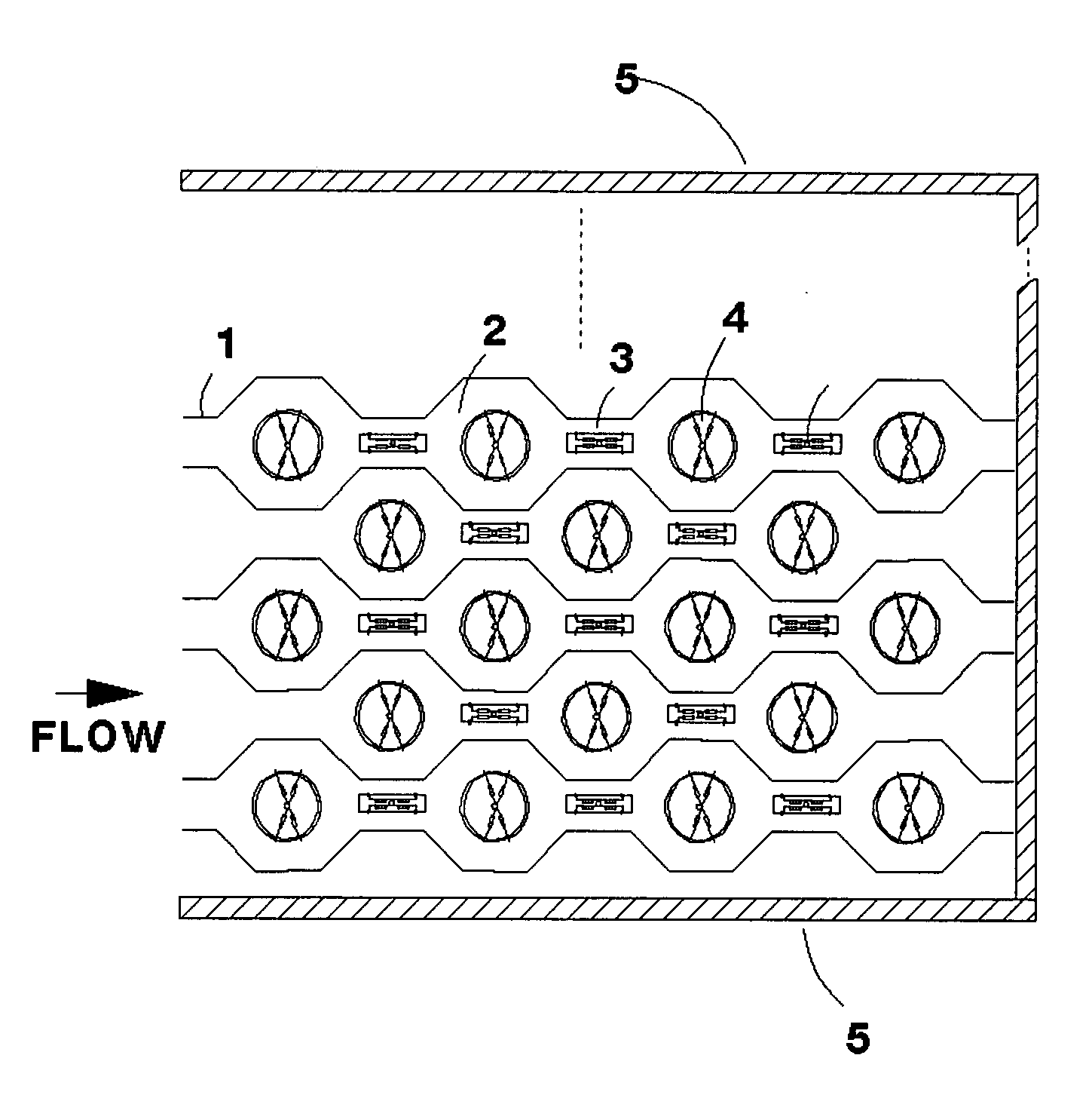
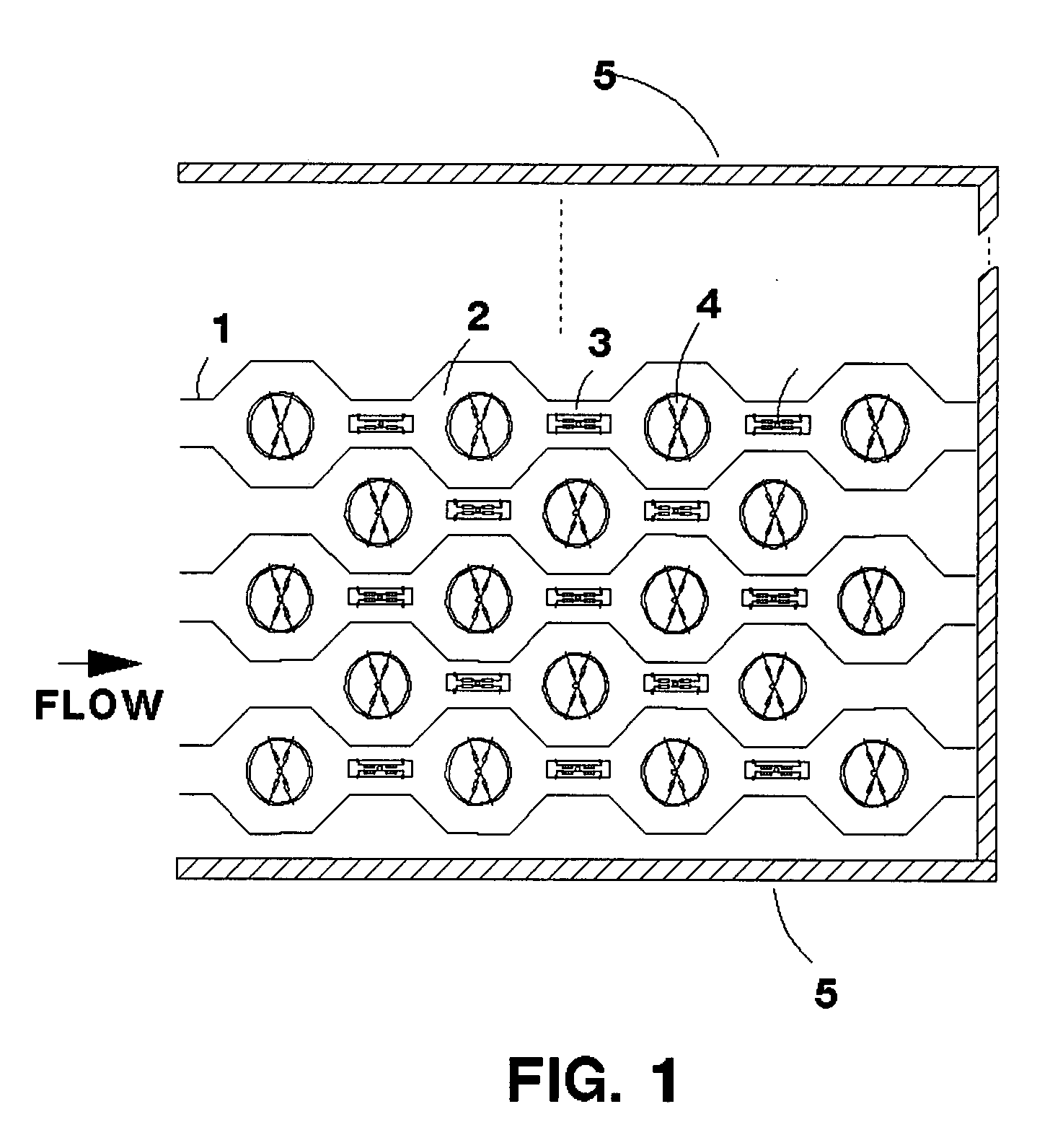
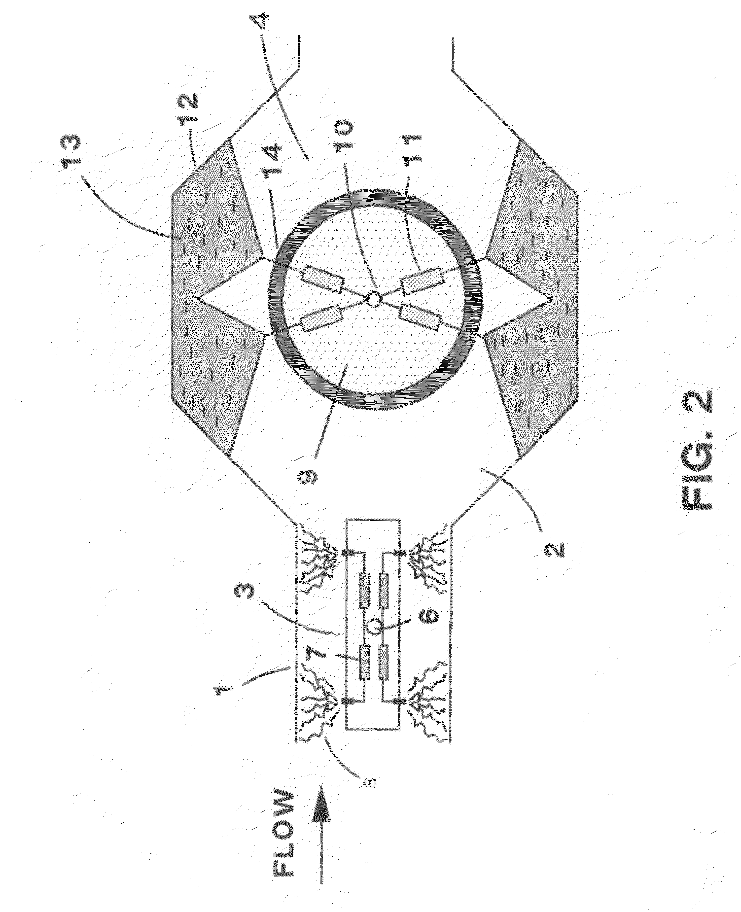
[0009]The present invention relates to advanced technology for the simultaneous removal of multiple pollutants from flue gas. The present invention relates to the simultaneous use of 1) steady-state diffusive glow discharge, 2) steady-state positive streamer corona along with the use conventional particulate collection techniques to optimize the efficiency of a precipitator. A new form of atmospheric pressure gas discharge called steady state glow discharge can dramatically increase the average electric field strength in a precipitator which in turn can increase the efficiency of the precipitator. Steady-state positive streamer corona can generate effectively chemical active species in the effluent gases. This can increase the removal efficiency of hazard pollutants. The present invention allows the use of a single DC or AC power supply to provide the different types of discharge and to provide linear electric field collection.

Problems solved by technology

Unfortunately, the energy producing industry is inevitably associated with emissions of vast amounts of dust, heavy metals such as mercury and various harmful gaseous contaminants such as sulfur dioxide and oxides of nitrogen.
These two gases are major anthropogenic acid gases that lead to the formation of acid precipitation and photochemical smog and have an adverse effect on human health and on vegetation.
Unfortunately, SO2 and NOx coexist in flue gases in many cases, such as the combustion of heavy oil, diesel fuel and coal.
The need for separate removal of pollutants is a major weakness of current methods.
However these types of discharges have intrinsic limitations associated with necessity to use narrow inter-electrode gaps and short high voltage pulses for the DBD and PCD respectively that results in difficulties in introducing these sources into real practice.

Method used


Image

  • Multi-stage collector for multi-pollutant control
  • Multi-stage collector for multi-pollutant control
  • Multi-stage collector for multi-pollutant control

Examples


Embodiment Construction

[0018]The present invention makes use of non-thermal plasmas (NTP) to destroy harmful gaseous components. An NTP can be created by different gas discharges (DC, AC or pulsed) at atmospheric pressure. Prior art methods of creating an NTP are dielectric barrier discharge (DBD) and pulsed corona discharge (PCD). DBD and PCD have intrinsic limitations associated with necessity to use very narrow inter-electrode gaps and very short high voltage pulses (for DBD and PCD respectively) that results in difficulties under introducing these sources into real practice. An NTP in flue gas is a quasi-neutral mixture of charged particles (electrons, positive and negative ions), chemical active particles like radicals and photons. Photons are created due to collisions of energetic electrons with molecules of the background gas. A very useful property of an NTP is that the majority of the electric energy deposited in the treated gas goes into heating the electrons rather than heating the gas. The typ...


PUM


Abstract

A multi-stage collector for multi-pollutant control that contains alternating narrow and wide sections with glow discharge electrodes in some narrow sections, a uniform electric field in wide sections for collecting particles charged by the glow discharge and streamer discharge electrodes in wide or narrow sections that convert and destroy harmful gaseous pollutants such as SO2, NOx and volatile organic compounds as well as convert heavy metals such as mercury into a particulate form. Steady state streamer discharge is supported by non-pulsed power supply. The streaming discharge can convert the polluting gases into nitric and sulfuric acid which can be removed by combining it with ammonia to form solid salts.

Description

[0001]This application is related to and claims priority from U.S. Provisional Patent application No. 60 / 853,954 filed Oct. 24, 2006. Application 60 / 853,954 is hereby incorporated by reference.BACKGROUND[0002]1. Field of the Invention[0003]The present invention relates generally to pollutant removal from industrial gas outputs and more particularly to a multi-stage collector for multi-pollutant control.[0004]2. Description of the Prior Art[0005]Ever increasing energy consumption is a fact of life. Unfortunately, the energy producing industry is inevitably associated with emissions of vast amounts of dust, heavy metals such as mercury and various harmful gaseous contaminants such as sulfur dioxide and oxides of nitrogen. These two gases are major anthropogenic acid gases that lead to the formation of acid precipitation and photochemical smog and have an adverse effect on human health and on vegetation.[0006]Traditionally, individual removal of either sulfur oxides (SO2) or nitrous ox...

Claims


Application Information

Patent Timeline
IPC IPC(8): B03C3/38
CPCB03C3/08B03C3/12B03C2201/30B03C3/47B03C3/383Y10S55/38
Inventor KRIGMONT, HENRYAKISHEV, YURI
Owner ALLIED ENVIRONEMTAL TECH
Learn More